

In suspension bridges, the humble cable clamp carries an outsized responsibility. These steel components grip the bridge’s main cable and hand off the load of every suspender, the vertical hangers that connect the deck to the cable above. Because the main cable slopes at an angle wherever a clamp is installed, each suspender force splits into two parts: one pressing perpendicular to the cable and another pulling downslope along the cable axis. That downslope component is the danger. If friction between the clamp and the cable cannot resist it, the clamp slides, and in a self-anchored suspension bridge studied previously with finite element modeling, slippage was found to triple the torsional moment on the stiffening girder, a serious safety problem. A new comparative study published in Advances in Bridge Engineering examines how two common clamp designs, pin-connected and saddle-type, respond differently to suspender forces, and finds that the same force that weakens one clamp strengthens the other.
The research team, led by Pengfei Zhang and Wei Zhang with colleagues including Chenghong Shi, Haining Yu, Peng Chen, Ji Liu, Xiang Xu and Xizhi Li, combined theoretical derivation with refined local finite element simulation. Their starting point was Coulomb’s friction law, which states that the friction available at an interface depends on the normal pressure pressing the surfaces together and the friction coefficient of the contact. For a cable clamp, that normal pressure comes from two sources: the pretension in the high-strength bolts that squeeze the clamp halves around the main cable, and the component of the suspender force acting perpendicular to the cable tangent. Existing design codes handle these contributions unevenly. The Chinese Specifications for Design of Highway Suspension Bridges count only the total bolt pretension when calculating anti-slip resistance and ignore the perpendicular suspender component entirely. Eurocode 3 does consider that perpendicular component alongside bolt pretension, but offers only a theoretical expression without a detailed calculation method. The authors note that explicit comparative analysis of the two typical clamp forms under suspender forces had been lacking.
The theoretical work begins with an infinitesimal element of the main cable in equilibrium under the clamp’s contact forces. Treating the cable as a homogeneous solid cylinder and assuming the interaction is uniformly distributed along the cable axis, the researchers derive an expression for radial pressure that decays exponentially around the contact arc, reflecting how circumferential friction progressively transfers load between the clamp wall and the cable. Integrating this pressure distribution over the contact surface yields the total radial force produced by bolt pretension alone. The friction coefficient enters at two distinct points: a circumferential coefficient governing the pressure decay, commonly taken as 0.15, and an axial coefficient governing resistance to sliding along the cable. The study adopts 0.15 for both in its models, a value the authors describe as commonly adopted in the literature, while the friction coefficient between clamp and bolts was set to 0.6.
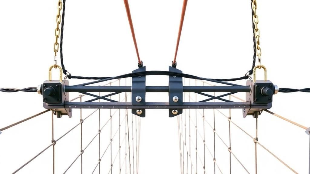
The two clamp geometries then diverge in how suspender forces modify this baseline pressure. A pin-connected clamp consists of an upper clamp, a lower clamp and bolts arranged on both sides of the main cable. The suspender force acts directly on the lower half of the clamp, and when the main cable makes an angle with the horizontal, the component of the suspender force perpendicular to the cable is proportional to the cosine of that angle. Solving the equilibrium equations for the lower clamp half produces an expression showing how the suspender force redistributes pressure between the upper and lower clamp pieces. A saddle-type clamp, by contrast, consists of left and right clamp plates with high-strength bolts symmetrically arranged above and below the main cable. Here the suspender wire rope passes over the upper part of the clamp, exerting inward pressure on the clamp’s outer surface, which is transmitted through the clamp to the main cable as an additional compressive force. The derivation follows the same pressure-decay procedure but integrates over the angular envelope of the wire rope, extending into the upper half of the clamp.
To test these formulations, the team built high-fidelity finite element models based on practical engineering cases. For the pin-connected case they selected an SJ1-type clamp located near the tower of a long-span suspension bridge, an upper-lower two-piece structure fastened by high-strength bolts. The modeled main cable segment was five meters long, with the central 1.6 meters inside the clamping zone. All components used eight-node three-dimensional solid elements, with the clamp pieces and bolts assigned an elastic modulus of 210,000 MPa and a Poisson’s ratio of 0.3. The main cable itself demanded more care: it was modeled with a tri-axially anisotropic material formulation in a cylindrical coordinate system, because the Z-direction along the cable axis carries axial tension through the wire properties while the radial and circumferential directions mainly resist interlayer and compressive forces. The equivalent moduli were set to 220,000 MPa radially, 360,000 MPa circumferentially and 1,900,000 MPa axially, with corresponding Poisson’s ratios of 0.26, 0.26 and 0.02.
The loading sequence mirrored actual construction practice, which the researchers argue matters for capturing the true stress state. In the field, the main cable is erected first, then the clamps and bolts are installed and tightened, and only then are the suspenders attached. The finite element analysis therefore proceeded in four steps: applying boundary conditions, contact definitions and the cable’s axial tension; applying the design bolt pretension of 900 kN per bolt; applying the suspender force; and computing the response. The suspender force of 1,250 kN was taken from measured average values, and the free end of the cable received a uniformly distributed surface load of 500 MPa to represent axial force. Surface-to-surface hard contact with the penalty method defined the interaction between cable and clamp and between clamp and bolts.
The validation results were close. For the pin-connected clamp under the 1,250 kN suspender force, the finite element integration of the pressure field gave a normal pressure between the clamp’s inner wall and the main cable of 20,463.73 kN, while the theoretical expression predicted 20,052.35 kN, an absolute error of 411.38 kN and a relative error of 2.01 percent. For the saddle-type clamp, modeled with hexahedral C3D8R elements for the main components and tetrahedral C3D4 elements in irregular regions near the clamp-cable interface, the simulation produced a normal pressure of 25,880 kN under the combined 1,250 kN suspender force and 14,400 kN total bolt pretension. The theoretical prediction of 24,741 kN differed by 1,138 kN, a relative error of 4.4 percent. Both errors fall within the five percent threshold the authors set as sufficient for engineering applications, and since the two models held every parameter constant except the clamp configuration, the comparison isolates the effect of clamp type itself.
With the formulas validated, the team used the theoretical solutions alone to sweep suspender forces from zero to 2,500 kN, twice the design level, under identical bolt pretension. The two clamp types moved in opposite directions. The pin-connected clamp’s anti-slip resistance decreased monotonically as suspender force increased, because the force acting on the lower clamp half reduces the effective contribution of bolt pretension in that region while simultaneously helping the upper half, with these opposing effects largely offsetting each other. At the design suspender-force level the pin-connected capacity had fallen by only about 15 kN relative to the zero-force condition, a reduction of less than one percent. The saddle-type clamp’s resistance increased monotonically, gaining approximately 311 kN, or about nine percent, at the design force, because the wire-rope pressure uniformly enhances the normal pressure on the clamp’s inner surface.
At the 1,250 kN design suspender-force level, the saddle-type clamp’s calculated anti-slip resistance came out approximately 9.6 percent higher than the pin-connected clamp’s. The authors frame this as a reference for cable clamp selection during the bridge design stage rather than a blanket prescription, and the conclusions carry the specific conditions under which the numbers hold: a total bolt pretension of 14,400 kN, a suspender force of 1,250 kN, an axial friction coefficient of 0.15 and the stated material assumptions, including the idealization of the main cable as a homogeneous cylinder and the neglect of bolt pretension eccentricity. The study is theoretical and numerical, validated against finite element simulation rather than physical slip tests on full-scale clamps, so the reported percentages are model predictions for the analyzed configurations. Still, the directional finding is clean and mechanically intuitive: how a clamp receives its suspender load determines whether that load erodes or reinforces the friction holding the bridge’s cables in place.
Subject of Research: Comparative theoretical and numerical analysis of anti-slip resistance in pin-connected and saddle-type suspension bridge cable clamps under suspender forces
Article Title: A comparative study on anti-slip resistance of pin-connected and saddle-type cable clamps in suspension bridges
Article References: Zhang, P., Zhang, W., Shi, C., Yu, H., Chen, P., Liu, J., Xu, X., & Li, X. (2026). A comparative study on anti-slip resistance of pin-connected and saddle-type cable clamps in suspension bridges. Advances in Bridge Engineering, 7(1), Article 21. https://doi.org/10.1186/s43251-026-00212-9
Image Credits: AI Generated
DOI: 10.1186/s43251-026-00212-9
Keywords: suspension bridges, cable clamps, anti-slip resistance, pin-connected clamps, saddle-type clamps, suspender forces, bolt pretension, Coulomb friction, finite element analysis, radial pressure, main cable, bridge design
News Source: Denise Maddox. (October 29, 2026). Suspender Forces Push Suspension Bridge Cable Clamp Types in Opposite Directions. Scienmag.