

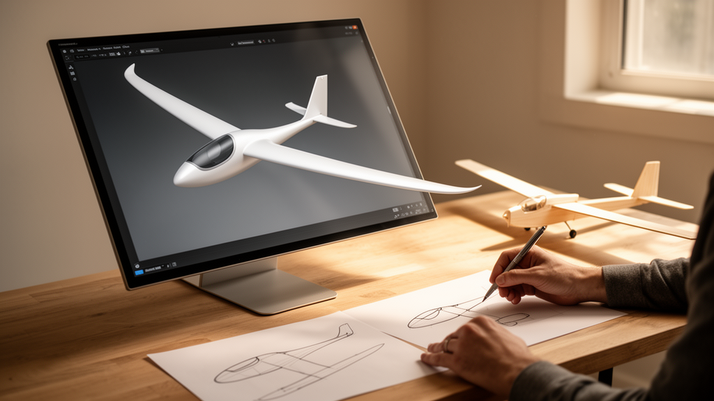
A pair of researchers has built a user-friendly software interface that estimates the optimal shape and performance of subsonic airplanes and gliders from just three basic inputs: the vehicle’s mass, the wing aspect ratio or wing area, and the altitude of cruise flight. The tool, described in an open-access paper published on 10 September 2026 in the journal Discover Vehicles, is aimed at the earliest, cheapest stage of aircraft design, where engineers and managers need quick answers without paying for complicated and expensive computational fluid dynamics simulations.
The work was carried out by Igor Nesteruk and Oleksii Dorozhkin, who combined low-fidelity approaches with analytical formulae for the drag of optimal wings and fuselages. In conceptual design, the goal is an initial estimate of characteristics such as shape, drag, power and range. The authors note that for a steady horizontal cruise, the drag on an optimal wing is practically independent of cruise speed, while the drag on the fuselage increases with speed. An optimal wing keeps the flow attached, so the pressure drag is close to zero and the wing drag reduces to the sum of friction drag and lift-induced drag. For fuselages, the interface recommends special unseparated shaped bodies of revolution, which wind tunnel tests reported in earlier studies show maintain attached flow and minimal volumetric drag coefficient at a specific relationship between speed, volume and length.
The mathematics behind the tool distinguishes between fully laminar and fully turbulent flow over the wing. For each case, the maximum aerodynamic efficiency of a slender wing, one whose thickness is much lower than the average chord length, follows a closed-form expression involving the wing aspect ratio, the vehicle weight, and the density and kinematic viscosity of air at cruise altitude. The interface interpolates standard atmosphere tables so users can enter any altitude in meters, or even supply their own values of air density and viscosity. A key result is that at fixed vehicle mass, the minimal drag on the optimal wing corresponds to the maximal aspect ratio, which is why record gliders with aspect ratios near 50 achieve weight-to-drag ratios near 70.
Real aircraft, however, cannot simply grow enormous wingspans. Strength and construction cost limit the aspect ratio, and so do takeoff and landing conditions, when the aircraft’s weight must be supported at speeds lower than cruise speed. The interface implements this constraint explicitly. If a vehicle must take off or land at a lower speed, the required wing area grows, and the software can compute that takeoff and landing wing area from the maximum possible lift coefficient of the chosen airfoil. By default the tool assumes a maximum lift coefficient of 1.8, a value the user can change; the authors note that a value of 1.2 was used in earlier work on the ETA glider, while 1.88 can be estimated for the Cessna-172R from its specifications. The default critical Reynolds number separating laminar from turbulent flow is set at 100,000, but users can enter other values, since specially shaped wings such as slotted natural-laminar-flow airfoils are reported to sustain laminar flow at Reynolds numbers above one million and lift coefficients above 2.
The code, written in MATLAB, was validated against the published specifications of existing vehicles: the Cessna-172R, the AN-24, the BN-2B Islander and the ETA glider. When the wing aspect ratio was fixed at the real value, the calculated optimal wing span and area for the Cessna-172R came out very close to the real figures, with differences below 1 percent for the optimal aspect ratio and span when wing area was fixed instead. For the AN-24 the differences ranged from about 8 to 16 percent in one mode of calculation and 15 to 32 percent in the other, and for the BN-2B Islander they reached 16 to 34 percent and 30 to 70 percent. The authors attribute the large discrepancy for the Islander to large laminar zones on its wing that the pure turbulent estimation does not capture, and they recommend CFD simulations to reduce the inaccuracy connected with the laminar-turbulent transition, which their analytical formulae do not reflect.
The ETA glider proved the most demanding test case. The optimal Reynolds numbers estimated with the laminar formula were too high for laminar flow, so the authors turned to the turbulent formula, which yielded differences of 12 to 25 percent at a speed of 30 meters per second and an altitude of 1.5 kilometers. The calculations also revealed how sensitive the optimization results are to the chosen conditions: at a cruise speed of 70 meters per second, the optimal wing span and area for the ETA came out far below its real figures, which the authors say explains the huge decrease in the glider’s commercial efficiency, or gliding ratio, at higher speeds. Because real aircraft are the products of optimization under many constraints, wing-only optimization can differ significantly from the wings of real vehicles, but the authors argue the approach is still well suited to conceptual low-fidelity design, redesign work and active morphing studies.
Fuselage design is handled through the special-shaped slender bodies of revolution proposed in earlier aerodynamic research. Given a desired fuselage volume, the interface recommends a length that minimizes the volumetric drag coefficient and calculates the resulting thickness ratio. Practical guardrails are built in: if the length-to-diameter ratio falls below about 3, the body is not slender enough to avoid separation and the drag estimates no longer apply, so the user is prompted to lengthen the fuselage; if it exceeds about 30, structural strength becomes a problem. A striking worked example concerns the Cessna-172R, whose non-axisymmetric fuselage probably experiences separation. Using the aircraft’s mass and a published weight-to-drag ratio of 10.6, the total drag comes to 1026 newtons; subtracting the average calculated wing drag of 372 newtons leaves about 654 newtons for the fuselage, empennage and interference. The authors show that the Cessna’s cabin could fit inside a special-shaped body of revolution 2 meters in diameter and 8.28 meters long, whose turbulent drag would be only 73.6 newtons, meaning a specially shaped fuselage could significantly cut the aircraft’s total drag even while offering larger, more comfortable cabins.
To demonstrate the tool’s reach, the authors calculated optimal characteristics for six new aircraft with masses ranging from 2 kilograms to 200 tonnes, using a turbulent flow pattern, an aspect ratio of 15 and a cruise altitude of 1.5 kilometers. The software recommends cruise speed and fuselage length from average aircraft characteristics, formulas the user can override. For the third design, a 200-kilogram vehicle, the optimal laminar fuselage with a length-to-diameter ratio of 5.13 can be designed to order. Adding two further inputs, the drag on other parts of the hull and the energy reserve convertible into mechanical energy, allows the interface to estimate engine power and range. In their calculations the authors assumed total drag is 1.2 times the sum of wing and fuselage drag, a factor the user can change; raising it to 1.5 would give 25 percent higher total drag and engine power and 25 percent lower commercial efficiency and range.
The range estimates are the headline numbers. According to the paper, rather high ranges of 200 to 600 kilometers were obtained even for electric vehicles with optimal wings and fuselages, assuming an energy reserve per unit weight of 30 kilometers, typical for battery aircraft with batteries making up about 30 percent of the vehicle weight. Switching to gasoline engines could increase the range approximately 15 times; for the 200-kilogram electric design the calculated range is around 350 kilometers, while a gasoline engine could push it beyond 5000 kilometers. The engine power estimate relies on an approximate relationship in which available power exceeds cruise power by a factor that varies only weakly with mass; for the Cessna-172R this formula predicted a ratio of 2.23 against an actual value of 2.48, a discrepancy of 10 percent that the authors take as evidence of the formula’s suitability for initial estimates.
The authors are careful about the tool’s boundaries. It applies only to subsonic vehicles with a classical wing-fuselage configuration and cruise speeds below 150 meters per second, and the estimations assume either fully laminar or fully turbulent attached flow, with CFD recommended to resolve the transition between the two. For the largest example aircraft, the recommended cruise speed of 173.6 meters per second exceeds the limit of the incompressible-flow approach, so the authors used 150 meters per second for reliable results. The software is still under development, and the final version is planned to work in an interactive dialogue mode in which the user enters a mass, receives recommended speed and fuselage length, and adjusts everything else. The authors hope the preliminary results will attract investors to support finalizing the software, and they present the interface as an easy and useful tool that lets engineers and managers find quick, effective solutions in the initial stages of design, long before any expensive high-fidelity simulation is warranted.
Subject of Research: Development of a low-fidelity software interface for conceptual aerodynamic shape design of subsonic aircraft and gliders
Article Title: Development of a user-friendly interface for conceptual shape design of subsonic airplanes and gliders
Article References: Nesteruk, I., & Dorozhkin, O. (2026). Development of a user-friendly interface for conceptual shape design of subsonic airplanes and gliders. Discover Vehicles, 2(1), Article 39. https://doi.org/10.1007/s44465-026-00037-w
Image Credits: AI Generated
DOI: 10.1007/s44465-026-00037-w
Keywords: aircraft design, aerodynamics, conceptual design, drag reduction, laminar flow, fuselage shape, wing aspect ratio, gliders, electric aircraft, range estimation, low-fidelity modeling, software interface
News Source: Audrey Campbell. (October 28, 2026). New Interface Speeds Up Conceptual Design of Subsonic Airplanes and Gliders. Scienmag.