


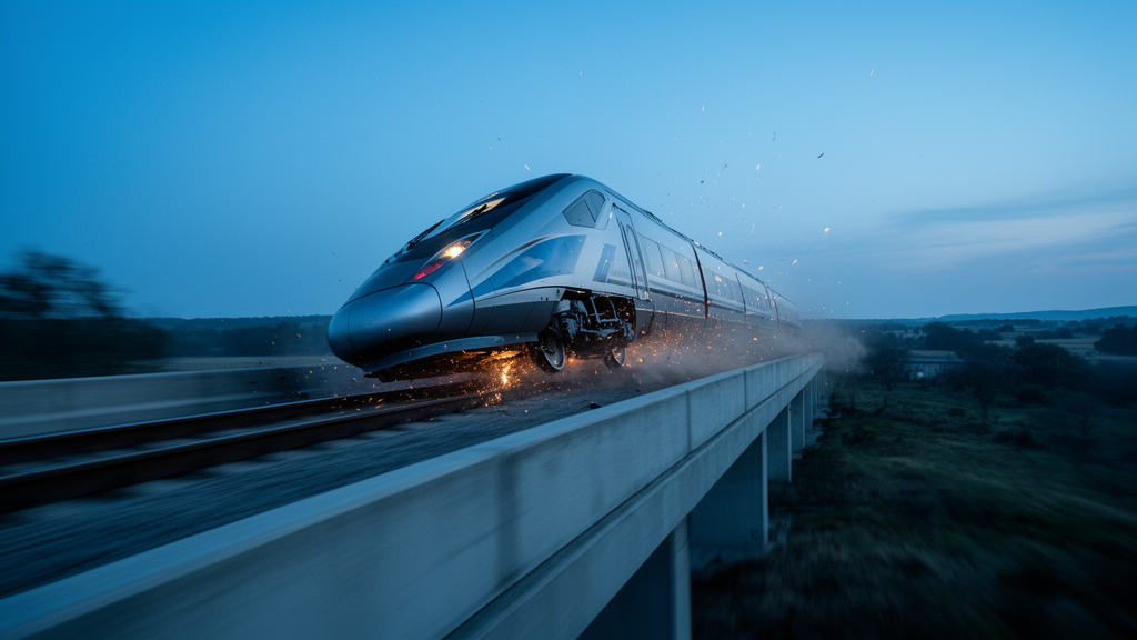
When a high-speed train strikes an obstacle on the track, whether it stays on the rails can depend less on how fast it was travelling than on the angle at which the impact arrives. That is the central conclusion of a new simulation study by Lingxiang Kong, Shuguang Yao, and Dongtao Wang, published in the journal Mechanical Sciences, which maps out for the first time a detailed derailment boundary for trains colliding with deformable obstacles. The work arrives at a moment when high-speed rail networks, particularly in China, are expanding rapidly and the consequences of a single derailment can be catastrophic.
The motivation for the study is sobering. According to the researchers, derailment accounts for as much as 60 percent of all collision-related railway incidents, and official reports from the Federal Railroad Administration identify unexpected obstacles intruding onto the track as one of the primary causes of sudden derailment during normal operation. The range of real-world hazards is broad: trucks stranded at level crossings, urban trams crossing main lines, deformed tunnel infrastructure, station platforms, bridge abutments, maintenance equipment left on the rails, and even large animals such as pigs, cows, and moose wandering into unfenced sections of track. The tragic derailment of Taiwan’s Taroko Express, which collided with a construction vehicle that had slid onto the rail and left more than 200 casualties, underscores how quickly such encounters can turn deadly.
What distinguishes the new work is its focus on deformable obstacles, which crumple and absorb energy during impact rather than behaving as rigid barriers. That deformation continuously changes the effective contact angle and the distribution of forces between train and obstacle, making the dynamics far more complex than a simple head-on crash. Most previous studies examined fixed collision conditions, and few had attempted to establish derailment boundaries or classify derailment modes for obstacles that deform. The team set out to fill that gap by systematically varying both the initial collision angle and the impact speed.
To do so, the researchers built a refined finite-element collision model in the LS-DYNA solver, comprising three interconnected subsystems: a three-carriage train, a deformable obstacle, and the rail. The train, a Chinese high-speed design with a top speed of 250 kilometres per hour, was modelled with a head car, a middle car, and a tail car, with a total collision mass of 167 tonnes calculated according to the European crashworthiness standard EN 15227, which specifies curb weight plus half the mass of seated passengers. The head car incorporated honeycomb energy-absorbing devices, a detailed body structure with a pilot frame, driver’s cab, and underframe, and bogies whose suspension was represented by six-degree-of-freedom discrete beam elements capable of capturing both spring stiffness and preload. Aluminium alloys 6005A-T6 and 6082-T6 were assigned to the body, stainless steel SUS301L_ST to the pilot frame, and a finer 10-millimetre mesh was used at the front of the vehicle where deformation concentrates.
Crucially, the model was not left unvalidated. The team compared their simulation against a full-scale impact test in which a real head car was fired into a rigid wall. The front-end deformation profiles and the contact force versus compression displacement curves from test and simulation showed a high degree of consistency, giving confidence that the numerical predictions of crash behaviour were physically meaningful. The obstacle itself was built to the geometry specified in EN 15227, with a stiffness calibrated by a separate impactor simulation that came out slightly above the standard’s prescribed value, and the rail was treated as a rigid body based on an established modelling approach.
The simulation matrix swept initial collision angles from 0 to 45 degrees and speeds from 110 kilometres per hour, the baseline in EN 15227, up to the train’s design speed of 250 kilometres per hour. The researchers tracked two classic safety indicators, the derailment coefficient, which is the ratio of lateral to vertical wheel-rail force with a limit of 1.2, and the wheel load reduction rate, limited at 0.65, alongside direct measurements of wheel vertical and lateral displacement. At a fixed 110 kilometres per hour, both indicators climbed steadily as the angle increased, and at 45 degrees all four wheels of the head car’s front bogie derailed. Yet between 0 and 40 degrees, no derailment occurred at that speed, even though the safety indices were frequently exceeded, a finding that exposes the limits of relying on the traditional indicators alone.
The detailed mechanics of the 45-degree case reveal how subtle the failure process can be. Roughly 0.03 seconds after impact, the left wheel of the first wheelset began to lift as its contact force fell to zero, while the right wheel’s forces spiked and rolled the wheelset to the right. The left wheel rose to 42.8 millimetres, above the 28-millimetre flange height, but then landed back on the rail and briefly ran normally before climbing the rail head and sliding laterally until contact was lost at about 0.21 seconds, a classic climbing derailment. The right wheel never lifted but slid sideways until it too lost constraint. The key insight is that exceeding the flange height is not sufficient for derailment; the wheel must also accumulate enough lateral displacement, in this case beyond a safe threshold of 55 millimetres, for the flange to escape the rail entirely.
Speed, examined at a fixed 0-degree angle, told a different story. As impact speed rose from 110 to 250 kilometres per hour, the front-end deformation grew progressively more severe, with the driver’s cab badly crushed at 170 kilometres per hour and compressed to half its size at 200. Wheel vertical displacements exceeded the flange height at speeds of 170 kilometres per hour and above, and at the full design speed of 250 both wheels of the first wheelset leapt dramatically, reaching heights of roughly 350 millimetres before falling back. Yet even in this extreme case, the wheels recovered normal contact and the train did not derail. Because a shallow-angle collision generates little lateral force, the wheels bounced but did not drift, demonstrating that derailment arises from the combined effect of lateral and vertical forces at the contact interface rather than either alone.
By stepping the speed up or down in 10-kilometre-per-hour increments at each angle, the team constructed a derailment boundary in the angle-speed plane, and its shape is striking. For angles of 5 degrees or less, the train never derailed, even at its full design speed of 250 kilometres per hour. At 10, 15, 20, and 25 degrees, the critical derailment speeds were 200, 190, 180, and 150 kilometres per hour respectively, and the failure mode was jumping derailment, in which wheels launch upward, fall back, and lose the rail through excessive lateral drift. At 30, 35, 40, and 45 degrees, the boundary dropped to 140, 150, 150, and just 50 kilometres per hour, with climbing derailment dominating as flanges ride up onto the rail head and slide outward.
The practical implications reach directly into infrastructure design and operations. Because shallow intrusion angles carry far lower derailment risk, the authors suggest the boundary can inform the layout of railway intersections and the placement of protective structures, while the sharply lowered speed thresholds at larger angles argue for reduced operating speeds at high-risk locations such as level crossings. The coupled angle-speed boundary also gives operators a quantitative tool for setting safety speed limits when obstacles are detected on the track. The researchers note that future work should extend the analysis to multi-hazard scenarios, coupling collision risk with natural disasters such as mudslides, earthquakes, and extreme weather, to quantify safety margins for the high-speed railways of the coming decades.
Subject of Research: Derailment mechanics of high-speed trains colliding with deformable obstacles at varying angles and speeds
Article Title: Mechanical responses of high-speed train derailment due to collision with deformable obstacles
Article References: Kong, L., Yao, S., & Wang, D. (2026). Mechanical responses of high-speed train derailment due to collision with deformable obstacles. Mechanical Sciences, 17(2), 769-782. https://doi.org/10.5194/ms-17-769-2026
Image Credits: AI Generated
Keywords: high-speed rail, derailment, collision dynamics, finite-element simulation, EN 15227, deformable obstacles, wheel-rail interaction, climbing derailment, jumping derailment, railway safety, level crossings, crashworthiness
News Source: Denise Maddox. (October 9, 2026). Collision Angle, Not Just Speed, Decides Whether a High-Speed Train Derails. Scienmag.