

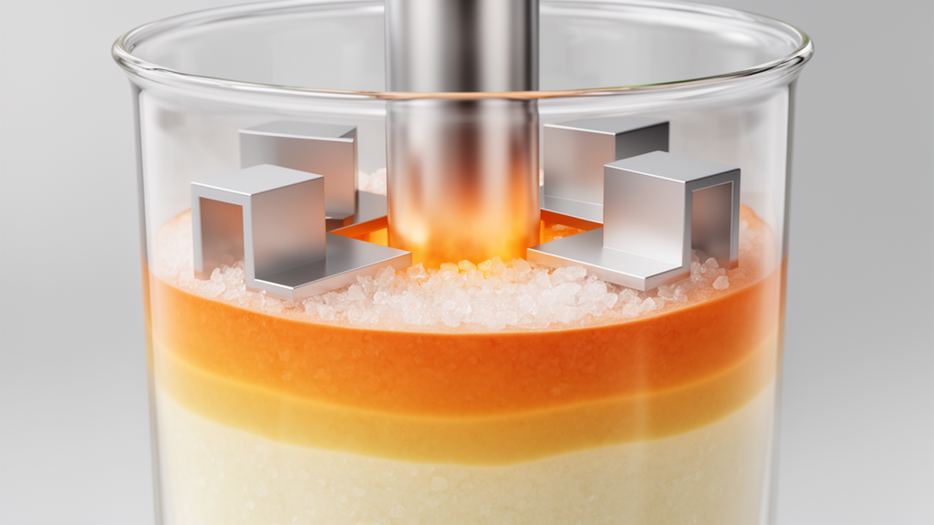
A computational study of a rectangular phase-change thermal energy-storage enclosure found that two aluminum L-shaped fins provided the best overall charging–discharging performance among four configurations tested. The device was modeled as a two-dimensional cavity measuring 60 mm by 140 mm and filled with Lauric-acid phase-change material. With the active wall held at 343.15 K during charging and 298.15 K during discharging, the two-fin design reduced the modeled charging time from 192.17 minutes in the finless baseline to 36.25 minutes and the discharging time from 1,607.3 to 1,223.3 minutes.
It also released the most energy per meter of enclosure depth and achieved the highest cyclic thermal efficiency among the simulated layouts, showing that the most effective design depends on balancing fin conduction, retained storage material and liquid circulation rather than simply adding more fin surface. The research used an enthalpy–porosity computational fluid dynamics model to represent the melting and solidification of Lauric acid. The PCM was treated as an incompressible, Newtonian, laminar medium, with buoyancy incorporated through the Boussinesq approximation.
Its phase-change interval extended from a solidus temperature of 316.65 K to a liquidus temperature of 321.35 K. Melting was considered complete when the domain-averaged liquid fraction exceeded 0.99, while solidification was considered complete when the average solid fraction exceeded 0.99. Carman–Kozeny momentum sinks damped flow in mushy and solid cells, while conjugate conduction was solved through the aluminum fins.
The cavity began fully solid at 298.15 K. During charging, the right vertical wall was maintained at 343.15 K while the left, upper and lower boundaries were insulated. Discharging began from the terminal charging field, or a nearly fully melted state, and the same active wall was reset to 298.15 K, below the Lauric-acid freezing interval.
The other boundaries remained insulated in both stages. Because the model was two-dimensional, energy and power were reported per meter of enclosure depth; end effects and depthwise circulation were not resolved. Four nested configurations were compared.
Case 01 was the finless baseline. Case 02 contained one L-shaped fin with a 132 mm vertical leg, a 52 mm horizontal leg and a thickness of 1.2 mm. Case 03 used two L-shaped fins, with leg dimensions of 132 by 52 mm and 88 by 40 mm; both were 0.6 mm thick.
Case 04 added a third, smaller pair of legs measuring 44 by 28 mm and reduced each fin’s thickness to 0.3 mm. This stepwise adjustment was intended to keep the PCM volume nearly similar among the finned cases, making it possible to compare fin geometry and conductive cross-section without treating a large change in material volume as the sole cause of performance. A single fin already produced a substantial change in the modeled thermal response.
Charging fell to 39.42 minutes, about 79.5% below the baseline, while discharging fell to 1,330.7 minutes, approximately 17.2% below the finless result. The two-fin configuration performed better across the complete cycle. Its charging time was another 8% shorter than that of the one-fin design, and its 1,223.3-minute discharging time was the lowest of the four cases.
It stored 1.8765 MJ per meter and released 1.7887 MJ per meter, corresponding to a cyclic thermal efficiency of 0.9532. Its average charging and discharging powers were also highest, at 862.78 and 24.37 W per meter, respectively. The three-fin configuration remained better than the finless baseline but did not surpass the two-fin design.
Its charging and discharging times were 115.75 and 1,347.7 minutes, and its cyclic efficiency was 0.9502. The simulations suggest that reducing each fin to 0.3 mm weakened its conductive cross-section even as additional surfaces were introduced. The extra solid boundaries could also restrict circulation in liquid regions.
In this model, therefore, adding more fin elements did not necessarily improve full-cycle performance once conduction, PCM volume and fluid movement were considered together. Transient fields illustrate two distinct roles for the fins. During charging, aluminum legs divided the original wall-driven melting front into several fronts and carried heat into areas that would otherwise remain conduction limited.
After local melting began, buoyancy-driven circulation around the legs redistributed heat through the liquid PCM. During discharge, the fins continued to shorten conduction paths and extract heat toward the cold wall, but their benefit was smaller. As solidification progressed, the growing solid layer suppressed natural convection and increased the resistance between the remaining liquid and the active wall.
Later-stage solidification was therefore more strongly conduction controlled than early-stage melting. Time histories supported this distinction. The finless cavity melted gradually as the front advanced from the hot wall, whereas the finned cases activated PCM around the fin network much earlier.
Wall heat-transfer rates peaked initially and then declined during both stages. During charging, the decline reflected a diminishing temperature difference as the adjacent PCM warmed; during discharge, it reflected increasing thermal resistance from the growing solid layer. Maximum fluid velocity increased after a liquid region formed during melting, but declined as the liquid volume contracted during solidification, indicating that natural convection made a larger contribution to charging than to the later discharge period.
Sensitivity calculations for the three-fin case showed that hot-wall temperature was the dominant influence on charging time. Raising it from 333.15 to 348.15 K reduced the modeled melting time from 51.40 to 18.50 minutes by strengthening both early conduction and later buoyancy-assisted transport. Cold-wall temperature had the strongest effect on discharge: increasing it from 293.15 to 308.15 K increased solidification time from 935.83 to 1,962.17 minutes.
Under the warmer discharge condition, recovered energy declined from 1,845.85 to 1,658.43 kJ per meter and cyclic efficiency fell from 0.9807 to 0.8811. Increasing the assumed latent heat from 170,000 to 200,000 J per kilogram raised stored energy from 1,748.76 to 1,984.15 kJ per meter and released energy from 1,650.34 to 1,887.29 kJ per meter, but lengthened both phase-change stages because more energy had to be absorbed and removed. The researchers then fitted quadratic response-surface models relating fin number and thickness to charging time, discharging time, stored energy and cyclic efficiency.
A central composite design supplied the modeling data, and a weighted Derringer–Suich desirability function combined the four objectives. The models for discharging time and cyclic efficiency showed strong agreement, with R² values of 0.9937 and 0.9995 and predictive Q² values of 0.9016 and 0.9930. The charging-time and stored-energy models also had R² values of 0.9182 and 0.9295, but each had a negative predictive Q², indicating weaker leave-one-out prediction.
Consequently, the continuous desirability maximum could not be presented as a statistically validated optimum. An apparent high-desirability region near three fins and a thickness of approximately 0.73 mm, with a composite value of about 0.895, was therefore treated only as a candidate for confirmation rather than the final design. Numerical checks supported the finest tested grid and two-second time step for comparative calculations, but they did not establish experimental accuracy.
Grids of 31 by 71, 45 by 105 and 61 by 141 control volumes produced charging completion times between 22.20 and 25.27 minutes for the representative three-fin case. The variation was not strictly monotonic, which the authors linked to changes in the alignment of the moving phase-change band and fin edges with grid faces. Time-step tests from one to four seconds produced values identical at the displayed precision, although rounding could conceal smaller transient differences.
Within the study’s stated limits, the direct comparison identifies two moderately thick L-shaped fins as the strongest full-cycle design among the cases actually simulated, not as a universal optimum for every enclosure. The model omitted radiation, fin–wall contact resistance, three-dimensional effects and experimentally measured property uncertainty, and its four prescribed layouts did not cover all possible fin topologies. Establishing a dependable continuous optimum would require a larger space-filling set of CFD cases, non-quadratic surrogate models, repeated cross-validation, confirmation simulations and three-dimensional experimental validation.
The central engineering result is nevertheless clear within the tested system: one fin provides a major charging benefit, while two preserve a more favorable balance of conduction, storage capacity and liquid-phase transport than three very thin fins.
Subject of Research: CFD optimization of L-shaped fins for full-cycle Lauric-acid phase-change thermal energy storage
Article Title: Multi-objective optimization of Lauric-acid PCM storage in a rectangular enclosure using L-shaped longitudinal fins: Mathematical modeling, design, and simulation
Article References: Rasool, G. (2026). Multi-objective optimization of Lauric-acid PCM storage in a rectangular enclosure using L-shaped longitudinal fins: Mathematical modeling, design, and simulation. Results in Engineering, 32, Article 113558. https://doi.org/10.1016/j.rineng.2026.113558
Image Credits: AI Generated
DOI: 10.1016/j.rineng.2026.113558
Keywords: Lauric acid, phase-change material, thermal energy storage, L-shaped fins, computational fluid dynamics, enthalpy–porosity method, multi-objective optimization, response surface methodology, natural convection, solidification, thermal conductivity, Multi-objective
News Source: Audrey Campbell. (October 21, 2026). Two L-shaped fins optimize Lauric-acid storage cycle in simulation. Scienmag.