


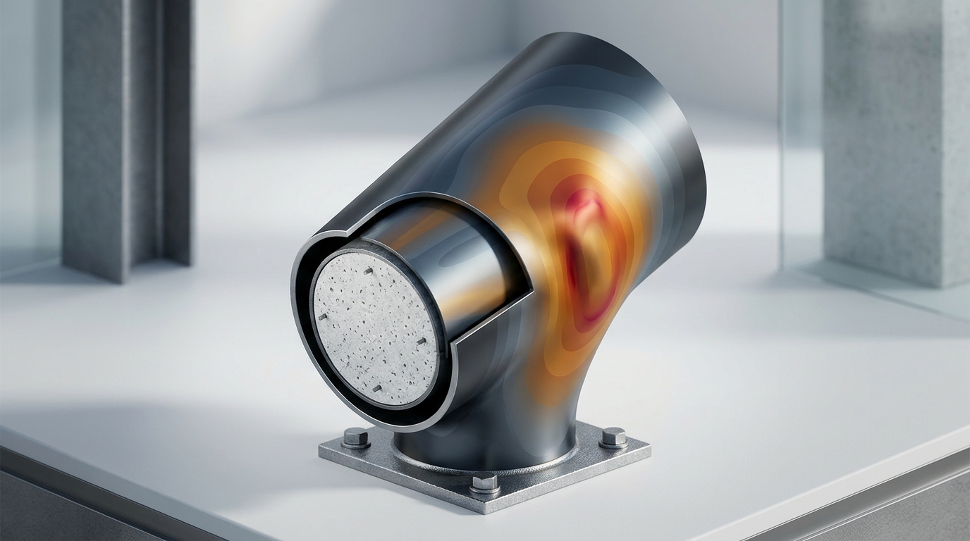
Concrete-filled double-skin steel tube columns are prized in tall buildings, long-span bridges and offshore platforms for their strength, ductility and stiffness, but a patch of corrosion or a drilled hole in the outer tube can quietly erode the margin of safety that engineers count on. A new experimental and numerical study has now mapped, in unusual detail, exactly where and how such local defects do the most damage to circular CFDST stub columns, and it offers a semi-analytical strength model that accounts for defect position and the local buckling it triggers.
The research team, led by Xi-Feng Yan of Case Studies in Construction Materials contributors including Rongli Li, Ji-Ping Hao, Siqi Lin and Yan-Gang Zhao, fabricated nine circular CFDST stub column specimens: eight with machined local defects on the outer tube and one intact control. Each column was 477 millimetres tall, roughly three times the outer diameter of 159 millimetres, with an outer tube of 159 × 5 mm and an inner tube of 76 × 5 mm, giving a hollow ratio of 0.5, a configuration previous work identified as an optimal balance of capacity, ductility and self-weight. The steel tubes were seamless to avoid weld effects, and the infill was C30 commercial concrete whose measured cubic compressive strength reached 45.3 MPa with an elastic modulus of 23.3 GPa. Tensile tests on coupon specimens cut from the tube skins gave yield stresses of 396.6 MPa for the outer tube and 423.1 MPa for the inner tube.
Defects in real structures rarely come in neat rectangles, so the researchers adopted the established simplification of idealising irregular corrosion patches, holes and notches as equivalent rectangular defects on the outer tube boundary, an approach validated in earlier studies. The test matrix varied four defect parameters: the concavity ratio, meaning how deep the defect is relative to the outer tube wall, at 50% and 100%; the vertical width ratio of the defect along the column, from 1/16 up to 1/4; the circumference angle of the defect zone, from 120° to a full 360° ring; and the axial position of the defect centroid, from 1/16 of the column height near the base up to the half-height. Defects were cut by lathe machining, a method whose feasibility earlier studies had verified.
Under axial compression in a 500-tonne servo-controlled machine, loaded at 0.2 mm per minute until displacement reached 20 mm or severe local deformation appeared, the failure patterns told a clear story. The intact reference specimen showed only slight local buckling, while every defective column developed pronounced outward local buckling right at the defect, where the thinned wall concentrates stress. Raising the concavity ratio from 50% to a full through-thickness opening of 100% changed the failure of the infilled concrete in the defect region from localised spalling to extensive crushing. Enlarging the circumference angle or the vertical width of the defect expanded the buckled region correspondingly in the circumferential and axial directions, and shifting the defect upward moved the buckling zone upward with it, confirming defect position as a key factor governing the failure pattern.
Strain gauges at mid-height and at the defect centroid revealed uneven strain distribution across defective cross-sections: strains were largest at the defect itself, smaller on either side of it, and smallest on the opposite side of the tube. The authors attribute the peak strain at the defect to the early onset of local buckling of the outer skin, which weakens the lateral confinement the tube provides to the concrete and degrades overall performance. Load–strain curves showed that defect parameters barely affected initial stiffness but flattened the post-yield branch noticeably, with the flattening growing as defects deepened, widened, lengthened around the circumference or moved toward mid-height.
Ultimate strength was defined at an axial strain of 0.01, a deformation limit commonly used in design practice for concrete-filled steel tube columns, since loads beyond that strain were stable or slightly increasing. A composite factor comparing measured capacity with a simple sum of steel and concrete contributions, and a defect reduction factor comparing defective with non-defective strength, quantified the damage. In the tests, pushing the defect depth ratio to 100% cut the reduction factor by 13.4% and the composite action by 13.6%, the largest single-parameter effect observed experimentally, which the authors link to the loss of wall thickness and the resulting weakening of the bond between outer skin and concrete.
To extend the findings beyond the nine specimens, the team built finite element models in ABAQUS using a five-segment steel constitutive model and a concrete damaged plasticity model, eight-node reduced-integration hexahedral elements, surface-to-surface contact with Coulomb friction and hard contact behaviour, and displacement loading through coupled reference points at the end plates. Validation against the experiments was strong: the ratio of predicted to measured ultimate loads averaged 1.01 with a coefficient of variation of only 0.03, and the models reproduced the observed damage patterns of three representative columns. A parametric study of 42 additional models, using larger columns 900 mm tall with 300 × 6 mm outer and 160 × 4 mm inner tubes, 355 MPa steel and 50 MPa concrete, then swept defect position from 0.1 to 0.5 of the height, vertical width ratio from 1/10 to 1, circumference ratio up to 0.75, and defect shape, expressed as the ratio of vertical width to circumferential arc length, from 0.01 to 3.10.
The numerical sweep sharpened the experimental picture. Moving the defect toward mid-height produced an essentially linear decline in both strength and composite action, and at a 100% concavity ratio located at half-height the reduction factor and composite factor fell by 3.7% and 6.1% respectively. Increasing the vertical width ratio first drove reductions down and then flattened out; at a width ratio of 1, the reduction factor dropped 15.9% for a 50% concavity ratio and 22.0% for a 100% one, with composite action falling 19.4% and 21.1% respectively. Circumference length ratio produced a roughly linear decline up to 0.75, with maximum reductions of 6.1% in strength and 4.3% in composite action. Defect shape showed a non-monotonic pattern: degradation was most severe near a shape coefficient of 0.77, with maximum reductions of 8.6% and 8.4%, and reversed as the shape approached 3.10.
Building on these results, the authors propose a semi-analytical strength model in which the capacity of a defective column equals the half-height defect capacity multiplied by a position influence factor that grows as the defect moves away from mid-height. The half-height capacity itself is derived from the ultimate strength of non-defective columns with reduced effective outer skin thickness, and the model explicitly accounts for the weakly constrained concrete zone created by the defect and by outward buckling of the adjacent intact tube, including cases where that zone reaches the inner tube and the central hole. Against both the experimental and numerical results, the model’s predictions averaged 0.984 of the measured strengths with a standard deviation of 0.041, slightly underestimating capacity, with individual ratios ranging from 0.907 to 1.070. The authors state the model applies to concavity ratios from 0 to 100%, defect positions from 1/16 to 1/2 of the height, vertical width ratios from 1/10 to 1, circumference ratios from 0 to 1, and shape coefficients from 0.01 to 3.10.
The practical message is pointed: for circular CFDST columns, the worst place for a defect is at mid-depth of the member, and the deepest, widest, longest defects around the circumference do the most harm, largely because they provoke early local buckling of the outer skin and strip confinement from the sandwiched concrete. The authors suggest the position findings can guide the selection of critical monitoring locations during the service life of CFDST structures such as wind turbine towers, bridge piers and offshore platform legs, where corrosion and drilled openings are routine. They caution that the study covered only circular short columns under axial compression, and that future work will extend the analysis to slender members and other cross-sectional configurations.
Subject of Research: Experimental and numerical study of how the position, depth, width, circumference and shape of local defects affect the compressive strength and local buckling of circular concrete-filled double-skin steel tube columns, with a proposed semi-analytical strength model.
Article Title: Local buckling-based semi-analytical strength model of circular defective concrete-filled double-skin steel tube columns
Article References: Yan, X.-F., Li, R., Hao, J.-P., Lin, S., & Zhao, Y.-G. (2026). Local buckling-based semi-analytical strength model of circular defective concrete-filled double-skin steel tube columns. Case Studies in Construction Materials, 25, Article e06682. https://doi.org/10.1016/j.cscm.2026.e06682
Image Credits: AI Generated
DOI: 10.1016/j.cscm.2026.e06682
Keywords: concrete-filled double-skin steel tube, local buckling, local defects, axial compression, semi-analytical strength model, finite element analysis, defect position, composite action, structural engineering, corrosion, ultimate strength, CFDST columns
News Source: Denise Maddox. (November 4, 2026). Defect Position and Local Buckling Drive Strength Loss in Circular Double-Skin Steel Tube Columns. Scienmag.