


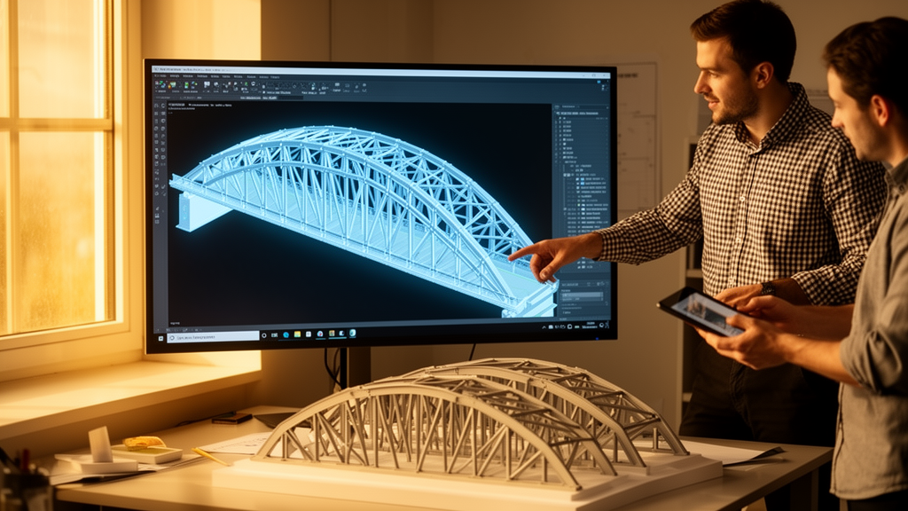
Engineers building a record-setting concrete-filled steel tube arch bridge in Chongqing, China, have shown that a digital workflow can replace slow, space-hungry physical pre-assembly for checking whether prefabricated arch rib segments line up correctly. Writing in Advances in Bridge Engineering, a research team reports that its virtual trial assembly method, built around three-dimensional laser scanning, achieved alignment accuracy within 2.6 millimeters while cutting measurement time to roughly one quarter of what traditional total station surveys require.
The method was developed and demonstrated on the main bridge of Shuangbao Bridge, which the authors describe as currently the world’s longest-span twin-arch bridge. The structure uses a twin-span continuous deck concrete-filled steel tube truss-arch system with variable depth, a design span of 405 meters, a rise of 80 meters, and a rise-to-span ratio of 1/4.75. Its main arch ring is a variable-depth spatial truss with a four-limb configuration, and the chord tube joints rely on internal flange bolting combined with external welding. Because the bridge has two spans, the number of segments is nearly twice that of a comparable single-span arch, which complicates fabrication yard logistics and makes physical pre-assembly especially demanding.
Traditional practice for verifying arch rib alignment relies on physical pre-assembly, in which segments are temporarily joined on a dedicated support frame before welding. The authors note that this process is time-consuming, labor-intensive, and space-demanding, driving up costs. After physical pre-assembly, inspection typically uses total stations, which take single-point measurements and cannot directly capture continuous axis-alignment data along the rib. Site size constraints also limit how many segments can be joined in each round, so traditional measurements assess alignment only within a single pre-assembly round, giving a local rather than an overall picture. Shuangbao Bridge used a “2 + 1” procedure in which three segments were assembled in sequence, welded at the flange joints, then dismantled segment by segment with one common segment retained for the next round, leaving inspectors with only single-point data per round.
Virtual trial assembly offers an alternative by using digital imaging, precise component measurement, reverse modeling, and computer-based simulation to stand in for physical pre-assembly. Three-dimensional laser scanners are the preferred measurement tool for this approach because they rapidly acquire high-precision point cloud data with low susceptibility to environmental disturbance. The new method begins with terrestrial laser scanning of the arch rib segments. Scan stations were arranged at four corner points according to the rib geometry, with two to three target spheres placed between adjacent stations to ensure seamless registration. The scan distance was 120 meters, with a resolution of 3.1 millimeters at 10 meters, and a densification scan of the flange plate was performed at 0.8 millimeters at 10 meters to support the assembly step. Noise was first removed using a bilateral filtering algorithm, and multistation scans were merged using the target spheres.
A central challenge lies in the flange plates that connect adjacent segments. Unlike welded connections, which tolerate limited offset, flange connections demand rigid butt-joint alignment, face to face and hole to hole. The researchers first tackle the substantial noise in flange-plate plane point clouds, which comes from the outer edge, the through-thickness region, and the bolt holes. Their singular value decomposition-based plane-fitting denoising algorithm fits a plane to the point cloud, removes points whose distance to the plane exceeds twice the fitting residual, and iterates until the change in fitting error between successive iterations falls below 0.1 millimeter and no such outlier points remain. The plane fitting is then repeated to obtain the optimal feature plane of the flange plate.
Next, an alpha shape-based feature extraction method identifies the flange plate contour and the bolt holes. The algorithm constructs a Delaunay triangulation of the projected point set, tests candidate boundary edges by drawing circles of a scale parameter set to the average point distance of the flange point cloud, and retains edges whose circles have empty interiors. Least-squares circle fitting then yields the flange plate center and the bolt hole centers, which serve as the assembly control points. Validation against Geomagic Control, a point cloud processing software for industrial small-part inspection, used 16 flange plates and 96 bolt holes on arch rib segment Nos. 1 and 2. Mean deviations between the proposed method and the benchmark in the three coordinate directions and in hole radius were 0.06, 0.07, 0.06, and 0.02 millimeters respectively, with maximum errors of −0.98, 0.67, 1.12, and −0.66 millimeters. For the bridge’s 52-millimeter bolt hole diameter, the maximum radius identification error was 1.26 percent.
With the features extracted, the virtual assembly proceeds in two stages that mirror the physical flange connection. Coarse assembly aligns the geometric centers of the four flange plates using an iterative closest point algorithm to estimate the rigid-body transformation of the incoming segment, with a penalty function applied to the distance residuals. Fine assembly then aligns the bolt hole centers, computing rotation and translation matrices through singular value decomposition of a covariance matrix and refining them iteratively until the matching error meets a preset threshold or the maximum iteration count is reached. In the field validation, the three directional errors of 24 matched bolt hole pairs from four flange plates were all within 1 millimeter, smaller than the allowable construction tolerance of 2 millimeters. Point-to-plane distance distributions after fine assembly peaked near zero, with a mean of approximately 0.3 millimeters for segment No. 2’s four flange plates relative to the reference plane, and the vast majority of points lying within 1 millimeter, indicating that the method controls flange assembly error at the submillimeter level.
Checking overall alignment requires extracting the axis of the arch rib’s main chord tube, a curved member with a near-circular cross section whose normal vectors vary continuously with position, complicating conventional geometric inspection. The standard approach slices the point cloud and fits the cross-section center, but accuracy depends on the slicing plane being perpendicular to the axis; an oblique cut produces an elliptical cross section and a biased center. The team turns this to advantage: least-squares ellipse fitting recovers the ellipse center, and the ratio of the tube radius to the ellipse’s semi-major axis gives the dihedral angle between the initial slicing plane and the plane truly perpendicular to the axis. Rodrigues’ rotation formula then computes the corrected plane normal, and a RANSAC-based planar circular fit on the reprojected points completes the axis extraction. Verification against total station measurements along the upper edge of the main chord tube, using first-round pre-assembly data, showed the extracted axis deviating from the total station result by less than 2.6 millimeters. A reverse-engineered solid model built from the extracted axis agreed well with the measured point cloud, with 90 percent of points lying between −1.3 and 2.6 millimeters.
Applied to arch rib segment Nos. 1 through 5 of Shuangbao Bridge, the method produced the overall alignment of the five pre-assembled segments. The maximum absolute lateral deflection deviation was 6.1 millimeters and the maximum absolute deviation of the intrados from the design curve was 5.2 millimeters, satisfying all alignment tolerance requirements, with a uniform distribution and no pronounced inflection points. For single-segment geometric dimension inspection, deviations of the four main chord tubes in the width and height directions stayed within the ±5 millimeter tolerance, with smaller deviations near the segment midpoint and slightly larger ones at the ends and local node areas, attributed to error concentrations during end assembly and member connections.
The efficiency gains are substantial. Under the traditional method, a four-person crew with a Leica TS60 total station needed about 5.5 hours to set out measurement points and arrange stations, 0.5 hours for setup, 4 hours for point-by-point observations, and 1 hour for data organization and post-processing, roughly 12 hours in total for one overall alignment inspection of three segments. By contrast, with a three-person crew and a Leica P50 terrestrial laser scanner, data acquisition takes about 0.5 hours per segment and processing about 1.5 hours, completing the inspection in roughly 3 hours, approximately one quarter of the traditional time. Once each segment’s point cloud is acquired, the method computes the overall alignment after multiple segments are connected directly, something conventional single-point measurements struggle to achieve, and can identify potential error transfer and accumulation across multi-round fabrication. The authors note the method is primarily intended for prefabricated segmental bridges whose segments connect through dedicated connectors such as flange plates, and that future work will target a virtual trial assembly workflow for welded connections.
Subject of Research: A virtual trial assembly method using 3D laser scanning to evaluate the alignment of prefabricated arch bridge segments
Article Title: Rapid alignment evaluation method for prefabricated arch bridges based on virtual trial assembly
Article References: Zhu, J., Zhuang, Y., Zhou, Y., Xin, J., Zhou, J., Luo, C., & Fan, Y. (2026). Rapid alignment evaluation method for prefabricated arch bridges based on virtual trial assembly. Advances in Bridge Engineering, 7(1), Article 27. https://doi.org/10.1186/s43251-026-00209-4
Image Credits: AI Generated
DOI: 10.1186/s43251-026-00209-4
Keywords: virtual trial assembly, prefabricated arch bridges, 3D laser scanning, point cloud, flange plates, alignment evaluation, Shuangbao Bridge, concrete-filled steel tube, axis extraction, total station, construction quality, bridge engineering
News Source: Denise Maddox. (October 30, 2026). Virtual Trial Assembly Speeds Alignment Checks for Prefabricated Arch Bridges. Scienmag.