


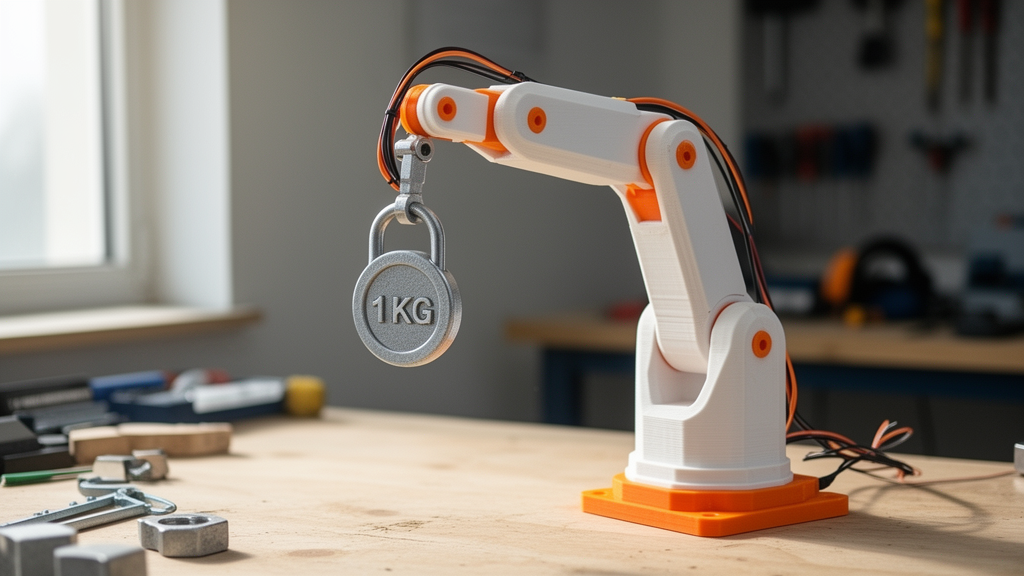
A team of researchers has designed, built and experimentally tested a low-cost robotic arm built almost entirely from 3D-printed parts, commodity stepper motors and an Arduino controller. The device, called the Smart Powered Lifting Robotic Arm, or SPLRA, successfully lifted and placed a 0.8-kilogram payload in all ten of its laboratory lifting trials, with no dropped loads, motor stalls, visible plastic deformation or loosened joints. The work, published as an open-access research article in the journal Discover Robotics, presents an unusually complete design pipeline for an affordable manipulator, running from first-principles torque calculations through computer-aided design and fabrication to measured payload, repeatability and electrical performance.
The motivation behind the project lies in a gap the authors identified across much of the low-cost robotics literature. Affordable robotic arms aimed at education, prototyping and light laboratory automation are typically demonstrated performing simple pick-and-place motions, but they rarely report quantitative payload tests, torque sizing, lifting-angle assessments or structural verification under repeated loading. Many published prototypes stop at computer-aided design models or simulations of lifting motions without physical tests of how payload and lifting angle interact. The SPLRA was conceived as an end-to-end framework that closes that loop: analytical actuator sizing, printable mechanical design, geared transmission, embedded control and empirical validation, all using hardware inexpensive enough for a teaching laboratory.
The mechanical architecture relies on SolidWorks for link and gear design, fused deposition modeling to print the components in PLA and PETG thermoplastics, and NEMA 17 stepper motors driving spur-gear transmissions. Control is deliberately simple: an Arduino microcontroller runs an open-loop scheme, issuing predefined step pulses for each joint, while users command the arm through a mobile application that talks to an HC-06 Bluetooth module over a 2.4 GHz link with a typical range of ten meters. The prototype was fed by a regulated 12-volt, 2-ampere supply for the motor driver circuit, with separate regulated logic power for the controller and wireless module. The arm offers between three and six degrees of freedom depending on the number of motors fitted, and its final assembly provides at least four degrees of freedom on a gear-driven rotating base.
A key conceptual move in the design was reformulating actuator sizing around electrical motor torque rather than the force calculations used for hydraulic or pneumatic actuators. For the reference lifting case of a 0.8-kilogram payload at a perpendicular moment arm of 0.2 meters, the static joint torque came to 1.57 newton-meters. Because the arm experiences acceleration, deceleration, gear backlash, vibration and uncertainty in load distribution, the team applied a dynamic load factor of 1.3, raising the service torque to 2.04 newton-meters. A 2-newton-meter stepper motor coupled through a 4:1 gear ratio at 75 percent transmission efficiency delivers roughly 6.0 newton-meters at the joint, giving an achieved actuator factor of safety of 2.94, comfortably above the design criterion of 2.0 adopted throughout the study.
That factor of safety of 2.0 was applied consistently to both actuator sizing and structural verification. Taking a conservative printed-material yield strength of about 50 megapascals for PLA and PETG, the allowable design stress was set at 25 megapascals. Analytical stress analysis under the same 0.8-kilogram loading used in the lift tests identified the long horizontal lifting arm, designated EBAarm2_006_horarm, as the most heavily loaded printed component, since it transfers the load through the greatest lever arm. Its peak calculated equivalent stress was 18.6 megapascals, corresponding to a factor of safety of 2.69 and remaining below the 25-megapascal allowable limit. The authors stress that this verification was analytical; a full finite element study with stress contours, displacement plots and convergence analysis is explicitly listed as future work.
The experimental validation focused on repeated lift-and-place cycles with the specified payload. Across ten trials at a target angle of 135 degrees, the arm achieved a 100 percent payload success rate, defined as completing each lift without payload drop, motor stall, visible deformation or stepping errors. Positional repeatability of the end effector was 2.47 plus or minus 0.58 millimeters, and angular repeatability was 0.41 plus or minus 0.23 degrees. The average cycle time per lift was 3.33 plus or minus 0.06 seconds. Because the printed spur gears were not measured for backlash separately, the reported positional error represents a system-level figure combining gear backlash, joint clearance, link flexibility, open-loop stepping and measurement error. Step loss, checked by confirming that each actuator reached its commanded position without stall or slippage, occurred in zero of ten trials, though the authors caution that this figure is constrained to the tested load, speed, voltage and laboratory conditions.
One of the more striking results concerns how lifting performance changes with angle. Lift time fell from 4.0 seconds at a 90-degree lift to 2.6 seconds at 180 degrees, while lifting height rose linearly from 15 to 30 centimeters across the same range. This follows directly from the torque relationship, in which the required torque scales with the cosine of the lifting angle: at 0 degrees the demand is the full 1.57 newton-meters, falling toward zero as the arm approaches vertical. The steeper the lift, the less resistance the motor faces, so the arm completes each cycle faster. The authors describe this as a mechanical advantage in near-vertical positions and suggest the angle-dependent profile can serve as a benchmark for programming efficient motion sequences and selecting motor acceleration profiles that avoid step loss.
Electrical validation addressed a practical concern: whether a modest 12-volt, 2-ampere supply could power four NEMA 17 stepper motors without overload. The answer depended on operating strategy rather than raw capacity. The motors were never driven simultaneously at their maximum phase current; instead, joints were activated sequentially, with the lifting joint and one supporting joint active during the main lift while the others held position at lower current or were deactivated. Current-limited stepper drivers, set via the driver reference voltage, capped phase current before testing. During the 0.8-kilogram lift, measured with an inline digital ammeter and a multimeter across the driver input terminals, peak current stayed within the 2-ampere limit and total input power remained below the 24-watt capacity of the supply. No controller resets, driver failures, stalls or skipped steps were attributable to voltage drop. The authors note that heavier loads, faster accelerations or simultaneous multi-joint actuation would warrant a higher-current supply, such as 12 volts at 5 amperes or more.
Durability claims are deliberately scoped. After the repeated lifting trials, the printed links, joint holes, gear interfaces and mounting regions were visually inspected, and no creep deformation, layer delamination, crack initiation, gear slippage, joint loosening or obvious mounting-hole elongation was found. The authors emphasize that this supports only short-cycle mechanical stability under the tested laboratory condition; extended cyclic loading tests were not performed, so the results say nothing about long-term fatigue life. Similarly, the prototype is a teaching-oriented device rather than a certified industrial robot. The team used the safety principles of the ISO 10218 robotics standard as guidance, limiting payload, running at slow speeds, restricting the experiment area and conducting tests in a controlled laboratory, but they make no claim of ISO compliance.
The authors position the SPLRA against the current state of the art in manipulation robotics, which increasingly features reinforcement-learning-based grasping, digital-twin-enabled human-robot collaboration and autonomous collision-free trajectory planning. The SPLRA deliberately does not include any of those capabilities; its contribution is confined to the mechanical and experimental validation layer: analytical torque and payload sizing, 3D-printed links and geared mechanisms, Arduino-based open-loop motion execution, Bluetooth control and measured lifting performance. Future work will add encoder-based closed-loop control for higher positioning accuracy, a complete finite element analysis of the most critically loaded links, and quantitative measurement of gear backlash, creep, delamination and fatigue under extended cycling. For laboratories and classrooms seeking a reproducible, low-cost platform that documents its own engineering margins, the SPLRA offers a template that connects every design decision, from gear ratio to power budget, to an experimental number.
Subject of Research: Design, prototyping and experimental validation of a low-cost 3D-printed lifting robotic arm
Article Title: Design and prototyping of a smart powered lifting robotic arm (SPLRA)
Article References: Ntambara, B., de Dieu Furaha, J., Masengo, G., & Niyigaba, J. B. (2026). Design and prototyping of a smart powered lifting robotic arm (SPLRA). Discover Robotics, 2(1), Article 17. https://doi.org/10.1007/s44430-026-00032-6
Image Credits: AI Generated
DOI: 10.1007/s44430-026-00032-6
Keywords: robotics, robotic arm, 3D printing, stepper motors, Arduino, actuator sizing, payload testing, PLA, PETG, open-loop control, Bluetooth, factor of safety
News Source: Denise Maddox. (October 30, 2026). Low-Cost 3D-Printed Robotic Arm Lifts 0.8 kg Payload With 100% Success. Scienmag.