


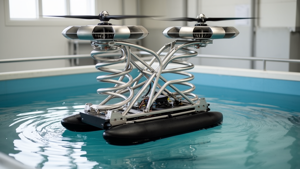
A computer-engineered folding arm can lift and rotate the rotor assemblies of a heavy-duty land-air amphibious vehicle using a single motor, according to a mechanical-design and simulation study. The proposed double-helical mechanism combines a vertically acting lead screw with a helical guide that converts the same upward stroke into horizontal rotation. In the prescribed multirotor flight condition, maximum stresses in the four mechanisms ranged from 165 to 195 megapascals, while maximum deformations ranged from 67 to 68 millimeters. These results came from one-way fluid-structure interaction analysis and indicated that the concept could withstand the modeled loading. The researchers cautioned that the complete flight-load envelope and a full-scale load-bearing prototype had not yet been tested.
The study addresses the configuration problem faced by a quadrotor-based vehicle intended to travel on the ground and operate in the air. Its four rotor-supporting arms must extend to a suitable flight configuration, but they also need to retract without interfering with the vehicle structure when the machine returns to road operation. The particular design requirement is simultaneous vertical lifting and rotation about a vertical axis: the rotor must move from a compact stowed position to a working position within the restricted installation space around the vehicle body. During retraction, the front arms move toward the front of the vehicle and the rear arms toward the rear. The rotors remain above the top surface of the vehicle throughout these transitions to avoid interference with the body.
At the center of the design is a nested assembly containing a lead screw, lifting platform, rotating sleeve, guide body and helical guide. A motor turns the lead screw through a speed-reduction and coupling arrangement, converting rotary input into vertical movement of the lifting platform. As the platform rises, the guide body travels along the inclined section of the helical guide. The guide converts part of the upward travel into rotation of the arm, coordinating lifting and steering without separate actuators for the two movements. The helical path includes an inclined segment for steering and a vertical segment for lift-stroke compensation, with the latter intended to reduce lateral friction. A compact hollow rotating sleeve serves as the nut in the screw transmission and is coaxially nested with the lifting platform. This arrangement facilitates force transfer, limits additional eccentric moments and improves integration within the available installation volume.
The lead screw was selected with several engineering constraints in mind, including axial load capacity, lead and stroke, driving torque, efficiency, resistance to back-driving and buckling, thread contact stress, manufacturability, maintenance and compatibility with the single-motor architecture. A high-strength guide rod is positioned beside the screw to help prevent nut rotation and reduce eccentricity in the thread engagement. The design also includes limit stops, locking components and a rotor-system connection interface. During deployment, the rotating sleeve, lifting platform and arm move upward together, while the guide body establishes contact with the helical path. The paper reports transitions in component loading as the guide body enters and exits the inclined segment, when the load changes from being carried primarily by the screw pair to being shared by the screw and guide constraint.
Actuation is deliberately separated from load bearing once deployment is complete. At the upper-limit position, a frustum-shaped hook engages with a corresponding locking interface on the vehicle body, creating a direct path for transferring flight loads rather than requiring the lead-screw transmission to support them continuously. The authors propose estimating deployment position through motor-encoder feedback and monitoring the locking state with position sensors. In the intended control system, a flight command would be enabled only when the deployment position and locking state satisfied predefined safety conditions; otherwise, flight operation would be inhibited. These monitoring and control functions are proposals within the design architecture rather than results from a flight-tested vehicle. The paper also notes that self-locking under the idealized model is achieved through motor-controlled preload, with the motor operating time extended to help ensure reliable retention.
Because the rotor arm’s center of mass lies away from the sleeve axis, its weight does not produce a uniform load on the limit-stop surfaces. The researchers modeled the annular contact interface with an equivalent linear contact-stiffness approach and solved force and moment equilibrium to estimate the pressure distribution. Their formulation divides the contact pressure into an average component and a linearly varying component caused by the arm’s eccentricity. Integrating this non-axisymmetric pressure field over the annular contact region yields the frictional resistance torque that the guide body must overcome during rotation. The resulting guide force adds to the axial load carried by the lead screw. This analysis identifies the guide-body root and the screw’s load-bearing section as critical regions for structural sizing, because the eccentric sleeve load is transferred through these components.
The researchers checked the analytical estimates against a dynamic model developed in ADAMS. Simulated lead-screw forces differed from theoretical results by 2.0% in the initial stage and 3.2% during the inclined guide segment. The guide-body force showed a larger discrepancy of about 10%, which the authors attributed to nonlinear contact, friction fluctuations and oscillation at the helical interface. The guide body entered contact during the inclined section, shared the load with the screw pair and then released the guide constraint as it exited. The lead-screw force remained comparatively stable outside those transitions, while the guide-body force returned to nearly zero outside the inclined segment. The authors describe the analytical model as useful for explaining the load-transfer mechanism and supporting preliminary sizing. For engineering verification, however, they recommend using simulated peak loads with a safety factor and then calibrating the estimates through prototype tests.
A reduced-scale model fabricated from polylactic acid with a 3D printer visualized the coupled motion. As the guide body moved from the bottom to the top of the guide, the deployable arm continued rising while rotating simultaneously. The physical model was used only for kinematic visualization and was not a load-bearing prototype. That distinction matters because the principal load results came from computational models rather than from a flight-tested amphibious vehicle. The dynamic calculations also used idealized assumptions, including a simplified constant friction coefficient. The authors identify friction coefficient, eccentric distance, helical lead and assembly clearance as variables that can influence the force estimates. They say sensitivity analysis and experimental calibration will be needed to develop correction methods and improve prediction accuracy.
To represent flight loading, the team first simulated the flow field around the quadrotor and extracted transient pressure and shear loads from the coupling surfaces. The four rotors followed similar lift histories as their rotational speed increased, with comparable stabilized thrust levels. Remaining fluctuations in the model were associated with transient wake development, dynamic-mesh effects and aerodynamic interaction among the rotors. These transient fluid loads, together with self-weight and structural constraints, were applied to the structural model of the mechanism. The procedure used one-way coupling: calculated structural deformation did not feed back into the aerodynamic field. Accordingly, the analysis evaluated mechanism-level structural response rather than full aircraft aeroelastic behavior. The fluid calculation used a pressure-based transient solver with a turbulence model, curvature correction, a turbulence production limiter, correlation-based near-wall treatment and a dynamic mesh combining smoothing and remeshing.
Under the modeled operating condition, the left-front, right-front, left-rear and right-rear mechanisms reached maximum equivalent stresses within the reported overall range of 165–195 MPa. Their maximum deformations fell within 67–68 mm. Stress peaks were concentrated in local connection and transition regions rather than distributed uniformly, while average stresses and average deformation were lower than the peaks. The four mechanisms showed no obvious stiffness imbalance or abnormal eccentric loading under the simulated condition, and the peak stresses were below the yield strength of the aluminum alloy 7075 assigned to the mechanism in the model. Carbon-fiber composite was considered as a possible material for a lighter main arm body, but the authors warn that composite behavior is anisotropic and that laminate optimization and joint-level analysis would be required before a quantitative comparison. Metallic or wear-resistant elements would still be needed at threaded, guide-contact and locking interfaces.
Together, the calculations support the feasibility of the double-helical architecture under the specified operating condition, not the existence of a flight-ready amphibious vehicle. The analysis did not encompass gust disturbance, asymmetric rotor aerodynamic interference, maneuvering acceleration loads, configuration-transition loads or two-way fluid-structure feedback. It also did not experimentally establish the repeatability of the proposed wear-control measures, which include hard anodizing or another verified surface treatment, replaceable wear liners or bushings, lubrication and periodic inspection. Untreated aluminum-alloy contact surfaces were not recommended for the final prototype. Planned next steps include a comprehensive flight-load spectrum, refined contact and friction models, two-way coupling with flight dynamics, closed-loop position and lock monitoring, and fabrication of a full-scale load-bearing prototype. Proposed tests would cover repeated deployment and retraction, drive-load measurement, static lift and torque loading, locking reliability, guide-interface wear, and comparison of measured performance with the simulation results.
Subject of Research: Mechanical design and flight-load analysis of a folding rotor-deployment mechanism for a land-air amphibious vehicle
Article Title: Design and analysis of a double-helical folding-deploying mechanism for a land-air amphibious vehicle
Article References: Gao, M., Zhang, M., Wang, M., Xu, P., & Sun, X. (2026). Design and analysis of a double-helical folding-deploying mechanism for a land-air amphibious vehicle. Frontiers in Mechanical Engineering, 12, Article 1915019. https://doi.org/10.3389/fmech.2026.1915019
Image Credits: AI Generated
DOI: 10.3389/fmech.2026.1915019
Keywords: double-helical mechanism, amphibious vehicle, rotor deployment, lead screw, helical guide, fluid-structure interaction, multirotor, mechanical analysis, structural stress, Design, analysis, double-helical
News Source: Denise Maddox. (October 20, 2026). Double-helical mechanism lifts and rotates amphibious vehicle rotors. Scienmag.