


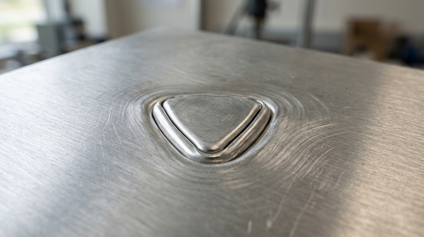
Researchers Deekshith Reddy Devulapally and Thomas Tröster have demonstrated through a three-dimensional finite element investigation that the rotational orientation of a Reuleaux triangle clinch joint significantly influences its mechanical load-bearing capacity under lap-shear loading. While mechanical clinch joints have traditionally relied on circular or rotationally symmetric geometries, investigating non-rotationally symmetric designs reveals critical orientation-dependent behaviors that can be harnessed in engineering design. The numerical investigation, published in Discover Mechanical Engineering, evaluated three distinct orientations of the constant-width geometry under quasi-static shear conditions while holding all other parameters constant. The simulations demonstrated that rotating the joint so that its curved arc faces the primary loading direction increases the sustained force at one millimeter of displacement by approximately ten percent compared to a vertex-loaded configuration. In contrast, joint orientation showed a negligible effect on initial elastic stiffness, varying by less than two percent across all configurations, demonstrating that rotational alignment governs plastic load capacity rather than elastic behavior.
Mechanical clinch joining serves as an established fastening technique across automotive body-in-white structures, domestic appliance manufacturing, and lightweight structural assemblies. Overall joint integrity, stiffness, ultimate load capacity, and energy absorption depend heavily on local geometric dimensions, notably the neck thickness and interlock depth established during forming.
Historically, research into clinching mechanics focused almost exclusively on circular punches and dies, optimizing process parameters, tool geometry, and forming conditions to improve material flow. Standard round joints, however, exhibit inherent limitations, such as negligible resistance to torsional loading and restricted performance in high-strength or thick sheet pairings. To overcome these constraints, researchers explored non-rotationally symmetric punch geometries, including rectangular tools for hard and thick sheet combinations and square geometries providing resistance to torsional loads. Subsequent studies on square clinching demonstrated that sheet stacking sequences strongly influence neck thickness, interlock dimensions, and overall joint strength. Building upon this progression, experimental work introduced the Reuleaux triangle geometry, proving through tensile shear, head tensile, and three-point bending tests that rotational alignment alters mechanical properties. Furthermore, multi-joint testing showed that orientation effects propagate to the assembly level, yet the underlying local stress and strain fields remained unresolved until this study.
The Reuleaux triangle represents a classical curve of constant width constructed from three circular arcs, each centered at a vertex of an equilateral triangle and spanning between the opposite two vertices. Consequently, its projected dimension remains identical in all directions between parallel tangent lines. In the analyzed joint model, both the arc radius and constant width equal 4.52 millimeters, joining two aluminum alloy sheets each measuring 2.0 millimeters in thickness. The forming die features a width of 7.2 millimeters with a tool depth of 4.16 millimeters. Optical microscopy of physically formed specimens verified baseline dimensions, revealing a bottom thickness of 0.34 millimeters. Crucially, the formed joint exhibits geometric asymmetry: neck thickness measures 0.29 millimeters on the vertex side compared to 0.47 millimeters on the arc side, representing a 62 percent increase in material thickness. Conversely, interlock depth measures 0.29 millimeters along the vertex side and 0.10 millimeters along the arc side.
To systematically analyze orientation effects, the researchers constructed a high-fidelity three-dimensional numerical model within LS-DYNA R13, adhering to the standardized lap-shear testing configuration outlined in the DVS/EFB 3480 specification. The virtual specimen featured a total length of 95 millimeters, individual sheet lengths of 55 millimeters, an overlap length of 16 millimeters, and a specimen width of 45 millimeters. Three specific orientations were evaluated by rotating the joint relative to the longitudinal loading axis: zero degrees, where a vertex faces directly into the loading direction; one hundred and eighty degrees, where the curved arc faces the loading direction; and ninety degrees, where neither feature aligns directly with the tensile axis. All boundary conditions, sheet dimensions, and solver definitions were held strictly constant across simulations, ensuring that rotational alignment acted as the sole independent variable governing mechanical differences, while inherently capturing the eccentric out-of-plane bending produced by the sheet neutral plane offset.
The modeled sheets consisted of EN AW-6014 T4 aluminum alloy, a precipitation-hardened material frequently utilized in automotive lightweight structures due to its favorable strength-to-weight ratio and formability. Material response was simulated using an elastic-plastic constitutive framework based on the tabulated Johnson-Cook hardening law, calibrated against experimental true stress-strain data up to the maximum available equivalent plastic strain. The elastic behavior incorporated a Young modulus of 63,000 megapascals, a Poisson ratio of 0.34, and a mass density of 2.700 times ten to the negative ninth tonnes per cubic millimeter. Due to the complex curvilinear profile of the Reuleaux boundary, the geometry was discretized using four-node tetrahedral elements with one-point nodal pressure formulations. Mesh sensitivity analyses evaluated joint region element edge lengths of 0.3, 0.2, 0.1, and 0.08 millimeters at zero degrees orientation, showing less than 0.1 percent variation in maximum stress. A refined 0.1 millimeter edge length within the joint produced a converged model comprising 1,200,833 elements.
Quasi-static lap-shear loading was simulated by fully constraining all six translational and rotational degrees of freedom at the lower sheet clamping region while applying a displacement-controlled motion of one millimeter along the longitudinal Z-axis to the upper sheet over a five-second duration. Computations utilized the LS-DYNA R13 implicit solver with a Newton-Raphson iterative convergence scheme, deliberately omitting mass scaling or artificial damping to maintain physical fidelity. Surface interactions between the upper and lower sheet components within the joint were captured using a mortar-based automatic surface-to-surface formulation. A friction sensitivity study across friction coefficients from zero to 0.15 revealed a 13.1 percent shift in absolute load level at one millimeter displacement, confirming that identical friction across orientations preserves the validity of relative comparisons. Zero friction between planar sheet interfaces was verified via a test simulation with a friction coefficient of 0.1, which yielded identical force-displacement curves. Tied mortar contact ensured kinematic coupling along the joint-sheet boundaries.
Across all three simulated orientations, the force-displacement responses exhibited monotonic, nonlinear hardening without a distinct bilinear transition, reflecting the progressive three-dimensional engagement of the mechanical interlock. These variations represent marginal increases of only 0.7 percent and 1.3 percent relative to the zero-degree reference. This relative insensitivity in the elastic regime stems directly from the constant-width geometry of the Reuleaux triangle, which presents an identical projected dimension along any orientation. In stark contrast, plastic load-bearing capacity at one millimeter displacement diverged markedly, recording 906 newtons for the zero-degree orientation, 950 newtons for ninety degrees, and 995 newtons for one hundred and eighty degrees, demonstrating progressive improvements of 4.9 percent and 9.9 percent as the contact geometry shifted from vertex to arc.
Examination of local field variables revealed that while all three orientations reached an identical maximum von Mises stress ceiling of approximately 312 megapascals, their internal spatial stress distributions differed substantially. In the zero-degree vertex-loaded configuration, stress concentrated severely into an acute band at the joint neck, generating steep stress gradients that accelerated plastic localization. In the one hundred and eighty-degree arc-loaded configuration, the contact force distributed across a broader arc perimeter, effectively dispersing stress and reducing local gradients. Analysis of normal stress along the loading axis confirmed concentrated compressive bearing on the vertex side for zero degrees and broadly distributed compression across the arc face for one hundred and eighty degrees. Furthermore, the 62 percent greater neck thickness on the arc side, measuring 0.47 millimeters versus 0.29 millimeters on the vertex side, provided a substantially larger cross-sectional area to sustain tensile forces, enabling the arc-aligned configuration to carry higher total loads before neck deformation was exhausted.
Contour analyses of effective plastic strain demonstrated peak values of 1.021 for zero degrees, 1.329 for ninety degrees, and 1.269 for one hundred and eighty degrees. The higher scalar peak strain observed at ninety degrees reflected localized strain concentration rather than a larger plastically deformed volume, whereas the one hundred and eighty-degree orientation distributed moderate plastic deformation across a wider neck volume, dissipating greater total plastic work. The authors emphasized that the investigation was purely numerical, evaluating a single material at 2.0 millimeters thickness without incorporating residual stresses, forming-induced work hardening, or ductile damage models, meaning the results indicate relative orientation-dependent performance rather than absolute failure loads. Nevertheless, the findings offer immediate practical value for structural engineering: in assemblies with predictable unidirectional shear loads, aligning the curved arc of Reuleaux triangle clinch joints with the primary loading axis increases joint capacity by approximately ten percent, achieved solely through precise rotational alignment of tooling during manufacturing.
Subject of Research: Finite element investigation of orientation-dependent mechanical performance in Reuleaux triangle clinch joints
Article Title: Finite element investigation of orientation-dependent mechanical properties in Reuleaux triangle clinch joints
Article References: Devulapally, D. R., & Tröster, T. (2026). Finite element investigation of orientation-dependent mechanical properties in Reuleaux triangle clinch joints. Discover Mechanical Engineering, 5(1), Article 187. https://doi.org/10.1007/s44245-026-00381-x
Image Credits: AI Generated
DOI: 10.1007/s44245-026-00381-x
Keywords: clinch joining, Reuleaux triangle, finite element analysis, lap-shear loading, aluminum alloy EN AW-6014, mechanical interlock, stress concentration, structural optimization, Finite, element, investigation, orientation-dependent
News Source: Denise Maddox. (November 8, 2026). Reuleaux Triangle Clinch Joint Alignment Enhances Load Capacity Under Shear. Scienmag.