

Electric propulsion systems have increasingly become standard drive technologies across modern satellite platforms, offering exhaust velocities and specific impulses that far exceed those achievable by conventional chemical thrusters. While chemical engines rely on thermal expansion of burned gases to generate forward thrust, electric engines utilize solar-electric power to ionize an inert propellant, predominantly xenon gas, and accelerate the resulting ions electrostatically. Because xenon undergoes no chemical reaction, the spacecraft consumes significantly less fuel mass over the course of a planned orbital mission. Modern electric architectures rely heavily on plasma-based configurations such as Hall effect thrusters and gridded ion thrusters, alongside electrothermal options like arcjets. In both Hall effect and gridded ion systems, ions are extracted directly from an active plasma discharge, while an external neutralizer cathode continuously emits electrons into the exhaust plume to balance charge loss. However, these systems inherently leak neutral gas through open channels or extraction grids, creating an unintended gas population directly in the path of the energetic exhaust stream.
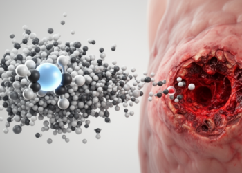
When accelerated primary beam ions collide with un-ionized neutral propellant atoms leaving the thruster exit, charge-exchange collisions produce low-velocity thermal ions that form an expanding secondary plasma cloud around the spacecraft. Because this secondary plasma naturally assumes a positive electrical potential relative to the spacecraft body, the cold ions are electrostatically accelerated back toward exposed satellite surfaces. Close to the thruster exit channel, local electrical potentials frequently remain several tens of volts above the satellite structure, providing sufficient energy for returning ions to strike exterior components above established sputter thresholds. This particle backflow introduces substantial operational risks to sensitive external payloads, including solar arrays, thermal control radiators, optical instruments, and mission electronics. The physical phenomenon of propulsion backflow was documented on early chemical missions and observed directly during historic flights such as Deep Space 1, which recorded thruster-induced current densities of 0.1 microamperes per square centimeter and detected sputtered molybdenum coatings deposited onto surrounding surfaces, as well as the SMART-1 mission, where an onboard diagnostic package measured returning ion energy peaks centered near 35 electron volts.
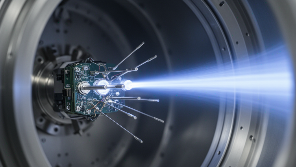
To rigorously characterize and monitor these surface-modifying interactions on future orbital missions, an academic and industrial collaboration comprising von Hoerner and Sulger GmbH, OHB System AG, and the Christian-Albrechts-Universitat zu Kiel developed a generic instrument suite termed the Electric Propulsion Diagnostic Package. The integrated package is scheduled for its maiden flight aboard the German Heinrich Hertz communications satellite, a mission managed under the industrial leadership of OHB System AG and funded by the German Aerospace Center to evaluate novel space communication hardware. The satellite platform incorporates two pairs of station-keeping thrusters for redundancy, pairing two Highly Efficient Multistage Plasma Thrusters from Thales Deutschland GmbH with two SPT 100 Hall thrusters from OKB Fakel. The flight diagnostic package consists of three main operational hardware elements: an integrated plasma sensor head combining a retarding potential analyzer and a plane Langmuir probe, a separate surface erosion sensor, and a central instrument control unit housing measurement electronics, voltage generators, and a field-programmable gate array powered by the standard 28-volt spacecraft bus.
Within the flight layout of the Heinrich Hertz satellite, the diagnostic elements are arranged behind the propulsion plane to monitor the dilute secondary backflow rather than being struck directly by primary high-speed exhaust plumes. The plasma sensor head is installed on an equipment radiator at a physical distance of 55 centimeters from the nearest thruster exit, orienting its 45-degree slanted entrance plane directly toward the center of the multistage plasma thruster nozzle. Across the opposite side of the spacecraft, the standalone erosion sensor is positioned in a comparable geometric location on an opposing radiator, while the electronics box resides shadowed on the rear face of the plasma sensor radiator. Because two discrete sensors cannot provide total spatial mapping across the entire spacecraft geometry, in-flight observational data from the package are specifically intended to anchor and validate comprehensive numerical simulation models of thruster-induced plasma environments, closing critical gaps between theoretical plasma expansion codes and authentic orbital performance.
The plasma sensor head integrates the retarding potential analyzer and the plane Langmuir probe into a single mechanical structure equipped with dedicated thermistors to track internal operational temperatures. The retarding potential analyzer serves as an electrostatic high-pass energy filter to record ion energy distribution functions from returning ions. It incorporates a stack of four titanium grids positioned above a segmented collector plate, located 22.9 millimeters behind a 14-millimeter entrance aperture. The outermost grid connects directly to spacecraft ground, ensuring that the sensor seamlessly matches the conductive satellite frame without disturbing the ambient plasma sheath. Behind this entrance, a dedicated repeller grid biased negatively to approximately minus 20 volts repels incident plasma electrons. A central discriminator grid sweeps positive voltages to selectively admit ions possessing kinetic energies above the barrier, while a fourth grid, held at the same negative potential as the electron repeller, reflects secondary electrons knocked loose from the collector plate back onto the collector surface to avoid erroneous positive current spikes.
To deduce the directional origin of incoming backflow particles, the collector plate situated beneath the retarding potential analyzer grid stack is segmented into four distinct conducting regions. Fabricated from a polyimide substrate coated with successive layers of 50 micrometers of copper, 5 micrometers of nickel, and 0.1 micrometers of gold, the collector features an insulated circular central segment surrounded by three outer ring segments separated by narrow, deep isolation grooves. The three inner titanium grids possess enlarged diameters of 19.3 millimeters, allowing ions with transverse velocity components to pass through the optical stack and strike the outer collector segments. A perpendicular ion beam deposits current almost entirely onto the central collector disc, whereas oblique ion trajectories generate asymmetrical current distributions across the three outer 120-degree sectors. Simultaneously, the top face of the sensor head incorporates a planar Langmuir probe consisting of a 20-millimeter circular collector surrounded by a coplanar guard ring measuring 42 millimeters in outer diameter, which minimizes edge distortions and enables precise determination of local electron densities and plasma potentials.
Alongside the plasma sensor, the diagnostic package includes a dedicated erosion sensor engineered to evaluate material loss caused by particle sputtering. The sensor monitors the electrical resistance of a thin conductive silver meander deposited over an area of 2 by 10 centimeters on a rigid rectangular ceramic carrier plate. The meander pattern measures 2 micrometers in thickness, 1 millimeter in width, and 180 centimeters in continuous total path length, establishing a baseline resistance of approximately 15 ohms to dominate harness wire resistance. Sputtering of metallic silver under particle bombardment thins the conductive track, increasing electrical resistance in direct proportion to material loss down to a measurement resolution of 10 nanometers. To accommodate severe orbital thermal cycling spanning from minus 80 degrees Celsius to plus 110 degrees Celsius, the ceramic plate is secured by flexible metallic mounting springs, while internal thermistor readings compensate for thermal resistance shifts. The system utilizes an alternating current four-wire measurement technique to filter out direct current offsets produced by thruster discharge currents and solar wind interactions, although it is strictly configured for erosion and cannot monitor material deposition.
Because reproducing the unconfined vacuum environment of space inside ground facilities is notoriously difficult due to chamber wall boundaries and elevated neutral gas densities, researchers designed a dedicated laboratory environment at the University of Kiel using a broad-beam microwave ion source. Operating inside a vacuum vessel at a xenon background pressure of 2.3 times 10 to the minus 2 pascals with a gas flow of 7 standard cubic centimeters per minute, the source extracted ions across three spherically curved graphite grids under 360 watts of 2.4-gigahertz microwave excitation. An 80-millimeter screen aperture restricted the beam core along an axis terminating at a low-sputter carbon fiber velvet dump. To imitate satellite backflow conditions, the engineering model of the plasma sensor was positioned in an offset location 18 centimeters away from the beam axis, tilted toward the aperture. The facility manipulated the secondary plasma potential in a controlled manner by applying bias voltages from minus 35 volts to plus 35 volts to a heated tungsten filament cathode positioned nearby.
Laboratory evaluation demonstrated that adjusting the hot cathode bias effectively regulates the surrounding plasma potential and corresponding secondary ion kinetic energies. When cathode voltages were maintained below zero volts, the secondary plasma potential remained clamped at 8.8 volts, exhibiting a diode-like behavior where thermionic electrons escaped freely to the chamber walls. Once cathode biases exceeded zero volts, emitted electrons became trapped by the wall sheaths, causing the local plasma potential to increase linearly with a slope of approximately 0.7 for both the onboard planar probe and an independent cylindrical reference probe. Concurrent measurements with the retarding potential analyzer showed that secondary charge-exchange ion energies remained stable at 8.3 electron volts under negative cathode bias, before increasing at a rate of 0.56 electron volts per volt under positive bias. Voltage sweeps across the retarding potential analyzer repeller grids confirmed that peak energy measurements varied by no more than one volt across a broad range, establishing that a repeller setting of minus 15 volts achieved optimal resolution and minimized peak width to 0.6 electron volts.
By operating the microwave ion source without an external extraction potential, the team established an idling beam environment where ions were accelerated solely by the internal source plasma potential of approximately 100 electron volts. Moving the retarding potential analyzer directly across this low-energy beam revealed a clear double-humped ion energy distribution function containing two distinct populations: low-energy secondary charge-exchange ions centered at 6.5 electron volts and primary beam ions centered at 107 electron volts. Comparing peak collector currents against an adjacent reference Faraday cup yielded an empirical calibration constant of 7.6 per square centimeter at zero discriminator voltage, a value confirmed independently when using argon instead of xenon, providing a reliable conversion factor to derive absolute ion flux densities from raw collector currents.
The engineering model and an earlier demonstrator model of the plasma sensor underwent further operational validation inside the Thales Deutschland test facility in Ulm, where they were operated alongside a flight-representative Highly Efficient Multistage Plasma Thruster inside a cryopumped vacuum chamber measuring 2.4 meters in diameter and 4.5 meters in length. The engineering model was placed in a representative flight orientation 36 centimeters from the plume boundary, while the demonstrator model monitored a position 55 centimeters away. Both sensors recorded double-humped ion energy distributions featuring an energetic peak centered at 85 electron volts with a 25-electron-volt half-width, alongside a secondary low-energy population extending below 60 electron volts with a maximum near 30 electron volts. Because geometrical shielding prevented primary beam ions from reaching the detectors, these measured energies correlated directly with charge-exchange ions originating in high-potential regions between the thruster exit and the neutralizer.
Simultaneous measurements using the planar Langmuir probes inside the thruster chamber recorded local plasma potentials of 6.2 volts for the engineering model and 7.2 volts for the demonstrator model, with electron temperatures of 2.3 and 2.2 electron volts and derived electron densities of 8.2 times 10 to the 13th and 5.9 times 10 to the 13th per cubic meter, respectively. Integrating the ion saturation currents from the planar probes indicated local ion flux densities of 5.9 microamperes per square centimeter for the engineering sensor and 3.8 microamperes per square centimeter for the demonstrator sensor. Applying the laboratory calibration factor of 7.6 per square centimeter to the retarding potential analyzer collector currents yielded a corresponding flux density of 3.2 microamperes per square centimeter. This close order-of-magnitude agreement between two distinct sensor operating principles confirmed the structural and electrical fidelity of the diagnostic instruments, verifying their readiness to monitor thruster-induced plasma interactions once deployed in orbit.
Subject of Research: Laboratory testing and validation of an in-flight electric propulsion plasma diagnostic package for satellites
Article Title: An in-flight plasma diagnostic package for spacecraft with electric propulsion
Article References: Trottenberg, T., Bansemer, F., Böttcher, S., Feili, D., Henkel, H., Hesse, M., Kersten, H., Krüger, T., Laube, J., Lazurenko, A., Sailer, D., Schuster, B., Seimetz, L., Spethmann, A., Weis, S., & Wimmer-Schweingruber, R. F. (2021). An in-flight plasma diagnostic package for spacecraft with electric propulsion. EPJ Techniques and Instrumentation, 8(1), Article 16. https://doi.org/10.1140/epjti/s40485-021-00073-8
Image Credits: AI Generated
DOI: 10.1140/epjti/s40485-021-00073-8
Keywords: electric propulsion, plasma diagnostics, retarding potential analyzer, Langmuir probe, erosion sensor, spacecraft secondary plasma, charge-exchange ions, ion energy distribution, Heinrich Hertz satellite, xenon ion thruster, Hall thruster, spacecraft charging, satellite surface erosion, vacuum chamber testing, Faraday cup calibration, plasma sheath dynamics, sputtering threshold
News Source: Ophelia Keating. (November 14, 2026). Engineers Validate In-Flight Plasma Diagnostic Package Designed for Electrically Propelled Satellites. Scienmag.