


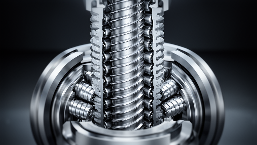
Mechanical engineers have developed a theoretical meshing framework that precisely computes the instantaneous contact line locations and total contact lengths across incomplete gear pairs in planetary roller screw mechanisms. The planetary roller screw mechanism operates as a high-precision transmission system converting rotational motion into linear displacement through the synchronized meshing of threaded rollers with either a surrounding nut or a central screw shaft. At the axial extremities of each cylindrical roller, integral spur gear teeth synchronize planetary motion, maintain precise kinematic positioning, equalize applied mechanical loads, and constrain axial and rotational degrees of freedom. However, because the helical thread profile of the roller traverses and physically truncates these terminal spur teeth during manufacturing, the resulting gear teeth are discontinuous along their width rather than unbroken involute profiles. This geometric interruption produces an axially discontinuous, intermittent meshing interface between the roller spur gears and their mating components—the internally toothed ring gear in standard planetary roller screw assemblies or the externally toothed screw gear in inverted designs. To clarify the contact behavior of these truncated teeth, the authors established coordinate transformations and spatial meshing equations that capture the geometric intersection between the helical thread and the spur tooth flank.
The mathematical formulation establishes local and global spatial coordinate frames to track tooth flank surfaces under rigid-body and ideal geometry assumptions. By setting the global coordinate systems alongside dedicated rotating frames for the roller, the ring gear, and the screw spur gear, the modeling framework maps how the surfaces interact across continuous rotation angles. The flank surfaces of the roller gear teeth are governed by involute surface equations constrained within axial intervals determined by the cutting profile of the roller thread. For radial distances from the roller axis that remain strictly smaller than the thread root radius, the involute tooth flank forms a continuous axial line across the entire face width. Conversely, once the radial coordinate exceeds or matches the thread root radius, the thread geometry cuts across the spur tooth flank, dividing it into discrete axial tooth segments. The researchers defined explicit parametric expressions to determine the axial boundaries of these intersected segments, capturing the exact spatial coordinates where the mating tooth surfaces satisfy tangential contact, position coincidence, common normal collinearity, and perpendicularity with relative velocity vectors.
By solving the common tangent relationship between base circles alongside the parametric surface equations, the analytical formulation evaluates the instantaneous meshing radius and the lengths of the active contact lines across every tooth. The contact line on any given spur tooth projects onto the transverse coordinate plane as a single focal point whose distance from the coordinate origin defines the operational meshing radius. When the meshing radius remains less than or equal to the thread root radius, the resulting contact line stretches across the full face width of the incomplete gear pair as an unbroken segment. When the meshing radius surpasses the thread root radius, the contact line fragments into discrete lines distributed across individual tooth segments. The overall contact line length for an engaged tooth then equals the cumulative sum of these truncated segments, bounded by the physical end faces of the gear blank. The authors established closed-form algebraic boundaries that directly compute the theoretical minimum and maximum aggregate contact line lengths across the entire range of operational meshing radii.
To evaluate the validity and accuracy of the theoretical model, the research team constructed internal and external three-dimensional finite element simulations within Abaqus using identical structural parameters. The numerical case studies evaluated a roller spur gear having 15 teeth and a 1.25 mm module meshing with a 225-tooth ring gear having an internal center distance of 133 mm in a standard mechanism, as well as with a 45-tooth screw spur gear at an external center distance of 38 mm in an inverted configuration. Across both models, the steel material properties were defined with an elastic modulus of 210 GPa and a Poisson ratio of 0.3. A rotational displacement of negative 0.84 radians was applied to the rotational degree of freedom of the roller spur gear across 21 equal increments while holding remaining axis rotations fixed, opposing an applied torque of 5000 N mm on the ring gear or negative 5000 N mm on the screw gear. Mesh refinement was applied directly to designated roller spur gear teeth to measure contact stress distributions, local meshing radii, and contact line lengths across the engagement cycle.
Comparisons between the mathematical formulations and finite element calculations demonstrated exceptionally close numerical agreement throughout the engagement sequence. Across the complete meshing cycle, the analytical model reproduced the meshing radius with a maximum relative error of 0.2104 percent for the standard assembly and 0.2844 percent for the inverted assembly, with corresponding mean relative errors of 0.0730 percent and 0.0845 percent. When evaluating the total contact line length across individual tooth flanks, the mathematical model exhibited a maximum relative error of 1.5559 percent in the standard mechanism and 1.9205 percent in the inverted mechanism, while average relative errors remained at 0.4932 percent and 0.4951 percent. Across both mechanisms, the maximum deviation in contact line length remained below 1.92 percent and the average deviation was under 0.50 percent, confirming that the analytical equations capture the contact geometry of incomplete gear pairs without requiring computationally intensive contact simulations.
The verification analysis also highlighted an operational characteristic regarding tooth engagement multiplicity during planetary roller screw operation. Throughout the entire analyzed rotation, only a single pair of gear teeth engaged in contact at any discrete load increment, preventing double-tooth meshing across the simulated steps. The researchers explained that this behavior is not a numerical defect, but rather stems directly from the truncation of the roller spur gear addendum by the outer boundary of the roller thread. This geometric truncation restricts the contact ratio of the incomplete gear pairs to 1.092 in the standard assembly and 1.049 in the inverted configuration. Consequently, the double-tooth meshing zone occupies an angular interval of only 0.0385 radians in the standard mechanism and 0.0204 radians in the inverted design, representing only 9.2 percent and 4.9 percent of the total meshing cycle. Because the numerical finite element model utilized a discrete load increment of 0.04 radians, this uniform increment exceeded the angular breadth of the multi-tooth contact zone, causing the finite element discretization to step completely past the double-tooth interval.
Parametric investigations into geometric variables revealed that the contact line length decreases substantially as the meshing radius expands from the tooth root toward the addendum. In the standard planetary roller screw configuration examined, increasing the meshing radius from 8.59 mm to 9.92 mm caused the minimum contact line length to decline from 18.00 mm to 3.28 mm, representing an 81.75 percent reduction, while the maximum contact line length fell from 18.00 mm to 3.75 mm, representing a 79.15 percent decline. Within the inner region where the meshing radius remains below the thread root radius of 8.95 mm, the contact line remains an unbroken segment equal to the complete face width of 18 mm. Once the meshing radius traverses the thread root threshold, the helical thread profile cuts into the active tooth surface, precipitating an abrupt drop in contact line length of approximately 20 percent. Beyond this root threshold, progressive radial expansion causes the helical groove to truncate an increasing proportion of the involute surface, driving further continuous reductions in contact length.
The study further demonstrated that the contact line length varies in a periodic, stepwise manner as a function of the gear face width, with the repetition interval matching the axial lead of the roller thread. When the face width is chosen to be an exact integer multiple of the thread lead—such as 2.4 mm, 4.8 mm, 7.2 mm, or 9.6 mm in the evaluated 2.4 mm lead design—the phase difference between the two end faces equals an exact multiple of 2π radians. Under this precise geometric alignment, both axial ends share identical thread phase positions, ensuring that every gear tooth around the circumference is truncated identically. As a result, the theoretical minimum and maximum contact line bounds converge, producing identical contact lengths across all fifteen roller gear teeth. When the face width deviates from an integer multiple of the lead, the individual teeth encounter differing thread phases, causing contact line lengths to diverge among adjacent teeth until the geometric discrepancy reaches a maximum at approximately half a thread lead.
The researchers also investigated how altering the roller thread profile radius across values of 13 mm, 14 mm, 15 mm, and 16 mm influences contact dimensions across different radial zones. In the root region near a meshing radius of 9.0 mm, increasing the thread profile radius from 13 mm to 16 mm narrowed the contact line length by 13 percent to 15 percent, with the minimum contact line experiencing a 15.21 percent reduction. Conversely, in the crest region at a meshing radius of 9.9 mm, the same increase in profile radius expanded contact line lengths by 115.78 percent to 125.74 percent. At a meshing radius of exactly 9.5 mm, corresponding to the pitch radius of the roller thread, the analytical curves for all four profile radii converged at an identical value, yielding zero relative change regardless of profile curvature. This localized behavioral inversion demonstrates that modifying the thread profile radius alters tooth engagement length unevenly across tooth positions, providing a design parameter for localized geometric fine-tuning.
While the mathematical model accurately resolves spatial meshing coordinates and contact line lengths, the authors noted specific structural and physical boundaries governing the current methodology. The analytical derivations are constructed on foundational assumptions of ideal geometric form and perfectly rigid mechanical bodies, intentionally excluding elastic tooth deflections, thermal expansions, manufacturing inaccuracies, mounting misalignments, and fluid lubrication films. Consequently, the derived contact line lengths serve strictly as geometric parameters rather than direct measures of operating contact stresses, load distribution patterns, or time-varying meshing stiffness. Future research efforts plan to build upon this kinematic framework by incorporating compliance, material elasticity, and physical machining deviations to conduct comprehensive loaded contact analyses of planetary roller screw incomplete gear pairs under demanding dynamic operational conditions.
Subject of Research: Kinematic modeling of incomplete gear pairs in planetary roller screw mechanisms
Article Title: A meshing model of the incomplete gear pairs in the planetary roller screw mechanism
Article References: Bu, X., Li, X., Wang, S., Fu, X., Liu, G., & Ma, S. (2026). A meshing model of the incomplete gear pairs in the planetary roller screw mechanism. Results in Engineering, 32, Article 114000. https://doi.org/10.1016/j.rineng.2026.114000
Image Credits: AI Generated
DOI: 10.1016/j.rineng.2026.114000
Keywords: planetary roller screw mechanism, incomplete gear pair, meshing model, contact line length, gear kinematics, roller spur gear, mechanical transmission, finite element analysis, meshing, model, incomplete, gear
News Source: Denise Maddox. (November 10, 2026). Analytical Model Resolves Contact Line Dynamics in Planetary Roller Screw Incomplete Gears. Scienmag.