

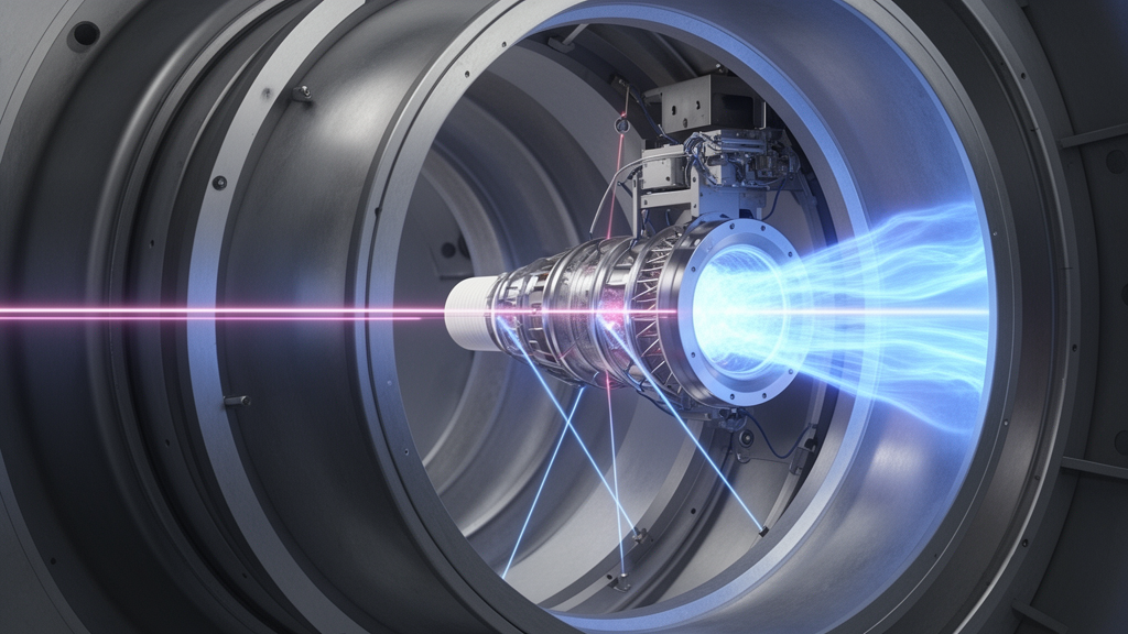
Researchers have evaluated two complementary in situ diagnostic instruments—a triangular laser head and an optical telemicroscope—to measure component erosion directly inside a space-simulation vacuum chamber during electric propulsion thruster testing. Electric propulsion engines generate thrust by accelerating charged particles, but their operational lifespans are fundamentally constrained by the structural wear of critical components, such as grid hole degradation in radio-frequency ion thrusters and ceramic channel wall erosion in Hall effect thrusters. Traditionally, verifying component wear requires halting tests, venting the chamber, and dismounting the engine for external profilometry or microscopy, a workflow that consumes several days per evaluation cycle and risks disrupting reproducibility. By integrating non-contact optical diagnostics into the vacuum test stand, the team demonstrated that radial and axial erosion metrics can be reliably tracked without breaking vacuum, preserving operational conditions and expanding characterization statistics.
The experimental investigation was performed within a large-scale vacuum test facility operated by Aerospazio Tecnologie, comprising a cylindrical chamber eleven point five meters long, three point eight meters in diameter, and one hundred and twenty cubic meters in volume. Supported by a xenon pumping system delivering effective speeds up to approximately two hundred thousand liters per second, the facility maintained an ultimate base pressure of eight times ten to the negative eighth millibar and an operating pressure of roughly four times ten to the negative sixth millibar during forty standard cubic centimeters per minute xenon flow. Both instruments were deployed on the Advanced Electric Propulsion Diagnostic platform, a modular five-axis positioning system engineered to manipulate diagnostic sensors around firing thrusters alongside plasma probes, retarding potential analyzers, thermal probes, pyrometers, and thermocameras.
The triangular laser head serves as a non-contact distance sensor designed to acquire surface topography by scanning across thruster components. During operation, an incident laser beam illuminates the test object, which scatters light diffusely. A fraction of this scattered light within a defined emission angle range enters the detection optics and is focused onto a position-sensitive detector. Variations in distance alter the entry angle, shifting the focal spot on the detector. Selecting a suitable laser head requires balancing measurement range, spot size, accuracy, sampling rate, physical compactness, and vacuum compatibility. While commercial triangulation heads are typically rated to fifty degrees Celsius and lack manufacturer vacuum ratings, long-term testing confirmed that customized housings and shielding permit reliable operation inside vacuum, provided direct exposure to the hot ion beam is minimized.
For experimental trials, the researchers selected a Keyence LK-G152 triangulation head offering a measurement range from one hundred and ten to one hundred and ninety millimeters, centered at a reference distance of one hundred and fifty millimeters. The sensor exhibited a spot diameter of zero point twelve millimeters at reference distance and a repeatability of zero point five micrometers. Encased in a metal housing measuring ninety-five by forty-seven by one hundred and twenty-seven millimeters with a graphite front shield and sapphire or glass windows, the unit utilized a custom multi-pin vacuum feedthrough. Because non-normal viewing angles cause optical refraction described by Snell’s law, test objects appear closer than their true geometric position. Calibrations established that window thickness and refractive index variations must be strictly controlled to maintain distance measurement accuracy better than plus or minus zero point zero three millimeters.
Operating alongside laser profilometry, the telemicroscope provides high-resolution optical imaging governed by classical thin-lens equations. The diagnostic assembly integrates an optical camera sensor, an optional extension tube, and an objective lens, with focusing achieved by adjusting relative physical distance rather than rotating lens barrels. Magnification relates the sensor dimensions to the captured object field of view, while lateral resolution depends on pixel dimensions, requiring feature separation across at least two pixels for definitive optical resolution. Axial resolution corresponds to the optical depth of field, defining the distance interval over which object details remain acceptably sharp. This depth depends on lens focal length, working distance, f-number, and the circle of confusion, an empirical value commonly estimated between one one-thousandth and one two-thousandth of the sensor diameter according to standard optical formulations.
For operational thruster evaluations, the researchers employed a DMK 41AF02 camera featuring twelve hundred and eighty by nine hundred and sixty pixels of four point sixty-five micrometers, coupled to a one-hundred-and-thirty-five-millimeter objective lens and a one-hundred-and-fifty-millimeter extension tube. This optical configuration achieved an extended working standoff distance of two hundred and fifty-six point five millimeters, delivering an eight point four micrometer lateral resolution and an idealized depth of field near zero point one millimeter. However, accounting for non-ideal thruster surface roughness and lighting conditions, practical axial resolution was determined to be approximately zero point five millimeters.
Over fifty cumulative testing hours, the non-contact instruments mapped structural features across the accelerator grid assembly. Diametrical scans recorded with the triangular laser head clearly identified the outer mounting ring, the grid rim, and the central perforated aperture zone, verifying that optical triangulation can track macroscopic thruster contours inside the vacuum chamber without requiring physical contact.
Despite its profiling precision, the triangular laser head encountered fundamental geometric limitations when scanning perforated ion grids. Where surface slopes exceeded the detection angle of the sensor optics, scattered laser light was shadowed by adjacent material, producing data dropouts near steep structural transitions. Additionally, sharp aperture edges caused optical scattering spikes, preventing direct measurement of individual grid hole erosion. Nevertheless, the instrument successfully captured dynamic changes in macroscopic outer grid curvature during thruster warm-up and cool-down cycles. Initial beam ignition caused an abrupt drop in grid curvature, attributed to electrostatic attraction between the high-voltage grids. Over subsequent operational hours, thermal expansion drove a gradual increase in curvature until thermal equilibrium was reached, after which thruster shutdown triggered an immediate curvature rebound followed by progressive relaxation during cool-down.
Telemicroscope imaging provided the optical resolution necessary to inspect individual RIT-22 grid apertures, but active engine operation introduced distinct optical complications. When the thruster was completely powered off, the telemicroscope resolved crisp grid hole boundaries, enabling precise geometrical evaluation of aperture wear. Conversely, during active plasma generation or ion beam extraction, intense optical emission from the excited xenon discharge scattered off the metallic hole perimeters, severely blurring structural edges on the camera sensor. These observations demonstrated that high-precision optical inspection of grid hole erosion cannot occur through the luminous discharge while the thruster is actively firing. Instead, reliable erosion inspections must be scheduled during brief engine shutdown intervals, allowing rapid optical assessments inside the chamber without breaking vacuum, venting the facility, or disturbing mechanical alignment.
The second experimental campaign examined an engineering model of the SPT-100D Hall effect thruster developed by Fakel, which utilizes dual hollow cathodes and operates at high specific impulse. The thruster was evaluated over approximately three hundred cumulative operating hours at power levels between thirteen hundred and fifty watts and nineteen hundred and fifty watts. Surface profiling with the triangular laser head combined approximately one hundred and fifty horizontal line scans spaced by one millimeter, reconstructing a comprehensive topographical map of the thruster face. The scans resolved the ceramic channel wall rings, the anode layer ring at the channel base, and central retention hardware. Detailed line scans across the channel rim revealed an initial phase of simultaneous radial and axial erosion, after which axial recession ceased while radial erosion continued monotonically over time.
Telemicroscope imagery of the SPT-100D channel walls confirmed the wear progression recorded by laser profilometry, tracking continuous radial erosion across evaluation milestones at one hundred and thirty-seven and three hundred hours. In addition to quantifying dimensional wear, optical imaging documented surface morphology transformations: initial mechanical grinding grooves across the ceramic face degraded into rough, granular microstructures under ion sputtering, while adjacent surfaces exhibited optical brightening indicative of redeposition or beam polishing. Axial erosion was tracked by shifting the telemicroscope focus along the eroded slope, matching laser data within the estimated half-millimeter axial resolution. Comparing both diagnostic approaches, the authors concluded that telemicroscopes provide superior radial erosion measurement on planar surfaces, whereas triangular laser heads deliver comprehensive three-dimensional profilometry across broader thruster geometries, provided steep-slope shadowing artifacts are carefully mitigated.
Subject of Research: In situ erosion diagnostics for electric propulsion thrusters using laser profilometry and telemicroscopy
Article Title: In situ erosion measurement tools for electric propulsion thrusters: triangular laser head and telemicroscope
Article References: Bundesmann, C., Eichhorn, C., Neumann, H., Scholze, F., Spemann, D., Tartz, M., Leiter, H. J., Gnizdor, R. Y., & Scortecci, F. (2022). In situ erosion measurement tools for electric propulsion thrusters: triangular laser head and telemicroscope. EPJ Techniques and Instrumentation, 9(1), Article 1. https://doi.org/10.1140/epjti/s40485-022-00076-z
Image Credits: AI Generated
DOI: 10.1140/epjti/s40485-022-00076-z
Keywords: electric propulsion, in situ diagnostics, triangular laser head, telemicroscope, ion thruster, Hall effect thruster, RIT-22, SPT-100D, surface profilometry, optical imaging, vacuum test facility, grid hole erosion, channel wall erosion, depth of field, Snell law, refraction correction, thermal expansion
News Source: Denise Maddox. (November 13, 2026). Optical Diagnostics Track Electric Propulsion Thruster Erosion Inside Vacuum Test Chambers. Scienmag.