


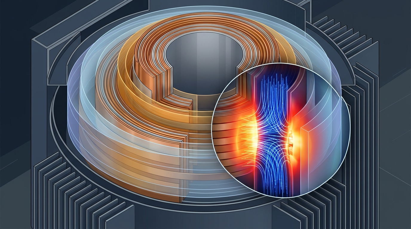
Dry-type transformers sit at the heart of modern power systems, prized for their safety and reliability, and the performance of their insulation directly shapes operational stability and service life. Yet while researchers have long probed how insulation structures fail under electric-field breakdown, a quieter question has gone largely unexamined: what happens to dielectric loss when the physical gaps inside the insulation system change size? A new simulation study from Wuhan University tackles that question head-on, building a two-dimensional axisymmetric finite-element model of the main insulation of a 10 kV dry-type transformer and tracing how two critical clearances—the LV-HV gap and the Fe-LV gap—reshape the electric field and, with it, the energy lost inside the insulation.
The research, led by Yanchen Wei, Linong Wang, Bin Song and Shaocheng Wu at Wuhan University’s School of Electrical Engineering and Automation, examines a chain that runs from insulation gap to electric-field distribution to dielectric loss. Rather than stopping at peak field strength, the team analyzed the full picture: how intense the field becomes, how evenly it is distributed, and how the energy integrated across the insulation volume translates into loss. The work appears in Frontiers in Electronics in the Power Electronics section as an original research article.
To quantify loss, the researchers employed the active/reactive power method, extracting volume loss density and terminal complex current from the simulation to calculate an equivalent dielectric loss factor for the main insulation. This approach links what happens locally—where energy is dissipated in the epoxy resin insulation—to what can be measured at the transformer’s terminals, giving the team a single figure that captures the dielectric behavior of the whole main insulation system as the gap geometry changes.
The headline finding concerns the LV-HV gap, the clearance separating the low-voltage and high-voltage windings. Within the simulated conditions, this gap exerts a strong influence on both field intensity and dielectric loss. When the gap was reduced from 21 mm to 13 mm at power frequency, the equivalent dielectric loss of the main insulation rose by about 52.5 percent. That is a substantial penalty for compactness: shrinking the gap by roughly 38 percent drives losses up by more than half, a trade-off that matters for designers trying to build smaller transformers without sacrificing efficiency or insulation life.
By contrast, the Fe-LV gap—the clearance between the iron core and the low-voltage winding—turned out to have a negligible effect on dielectric loss in the simulations. This asymmetry between the two gaps is one of the study’s most practical takeaways. It suggests that engineers seeking to trim dielectric losses should focus their attention on the LV-HV clearance, while the Fe-LV gap offers more freedom for geometric adjustment without a significant loss penalty.
To move beyond individual data points, the team fitted an empirical power-law correlation linking the LV-HV gap to dielectric loss at power frequency, using the three gap sizes examined: 13 mm, 17 mm and 21 mm. The authors are explicit about the limits of this fit. Because it rests on only three data points, they caution that it should be treated as a local interpolation rather than a validated quantitative law, and they warn against extrapolating it beyond the studied range. The correlation is a tool for the conditions tested, not a universal formula for every transformer design.
The study also highlights the role of field uniformity in dielectric loss regulation. How evenly the electric field spreads through the insulation matters, not just how strong it is at its peak. Non-uniform fields concentrate energy dissipation in localized regions, and the analysis of field distribution alongside peak field and energy integration gives a fuller account of why narrowing the LV-HV gap raises losses so sharply. This framing—examining peak field, field distribution and energy integration together—distinguishes the work from studies that consider breakdown alone.
For transformer designers, the results offer theoretical and simulation support for multi-objective optimization, balancing electrical strength, volume and operational loss. Choosing an insulation gap is not simply a matter of withstanding voltage; it is a compromise among competing demands. A larger LV-HV gap may improve electrical strength and reduce dielectric loss, but it costs volume. A smaller gap saves space but, according to these simulations, carries a measurable loss penalty. Quantifying that penalty—about 52.5 percent over an 8 mm reduction—gives designers a concrete number to weigh against the benefits of compactness.
The authors are careful to state the boundaries of their conclusions. All results come from two-dimensional finite-element simulations at 10 kV and have not been experimentally validated. The findings are therefore provisional and limited to the studied conditions. Real transformers involve three-dimensional geometry, manufacturing tolerances, thermal effects and material variability that a 2D axisymmetric model cannot capture, and the power-law fit’s three-point basis further restricts how far its predictions can be trusted. The study examines the chain from insulation gap through electric-field distribution to dielectric loss in terms of peak field, field distribution and energy integration, and its conclusions about field uniformity’s role in loss regulation remain within that simulated frame.
Even so, the work opens a direction that has received less attention than breakdown studies deserve company in exploring: dielectric loss as a design variable tied to insulation geometry. By showing that the LV-HV gap strongly affects field intensity and dielectric loss while the Fe-LV gap barely matters, and by providing a provisional quantitative relationship for the gaps tested, the Wuhan University team gives the field a starting point for optimization studies that treat loss, strength and size together. For a technology whose insulation performance directly affects operational stability and service life, that integrated view may prove as valuable as any single number the simulations produced.
Subject of Research: Electric-field distribution and dielectric loss in the insulation gaps of a 10 kV dry-type transformer modeled with the finite element method
Article Title: Study on electric field distribution and dielectric loss characteristics of insulation gap in dry-type transformer based on finite element method
Article References: Wei, Y., Wang, L., Song, B., & Wu, S. (2026). Study on electric field distribution and dielectric loss characteristics of insulation gap in dry-type transformer based on finite element method. Frontiers in Electronics, 7, Article 2004306. https://doi.org/10.3389/felec.2026.2004306
Image Credits: AI Generated
DOI: 10.3389/felec.2026.2004306
Keywords: dry-type transformer, dielectric loss, electric field distribution, finite element method, insulation gap, epoxy resin, LV-HV gap, Fe-LV gap, power electronics, simulation study, electric, field
News Source: Denise Maddox. (November 3, 2026). Narrowing insulation gaps in dry-type transformers raises simulated dielectric loss by 52.5%. Scienmag.